background image

Publication 2711C-QS001F-EN-P - November 2010

27

Make Terminal Connections        

Chapter 2

Configure Browser Settings

Browser changes are required before using the PanelView Explorer design environment. For optimal 
performance, the Internet Explorer 7 browser or the Firefox 2.0 or 3.0 browser is recommended.

All Browsers

1.

Verify that cookies are 
enabled. 

2.

Turn off the pop-up blocker.

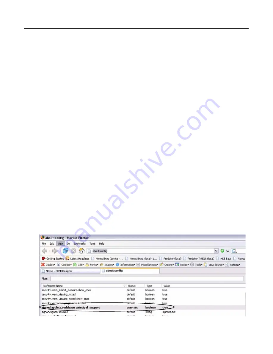
Mozilla Firefox 2.0 or 3.0

The Firefox browser requires changes before you can copy and paste data from a grid or state editor in 
PanelView Explorer to Excel. The browser requires a preference named 
signed.applets.codebase_principal_support. Without this preference, data will not paste into Excel. 

1.

Verify your Firefox browser 
is open.

2.

Enter the URL about:config.

3.

Look for the preference: 
signed.applets.codebase_prin
cipal_support

4.

If the preference name 
exists, skip to step 7..

Summary of Contents for 2711C-F2M

Page 1: ...Quick Start Catalog Numbers 2711C F2M 2711C K2M 2711C T3M 2711C K3M 2711C T6M 2711C T6C 2711C T6T 2711C T10C PanelView Component HMI Terminals...

Page 2: ...atent liability is assumed by Rockwell Automation Inc with respect to use of information circuits equipment or software described in this manual Reproduction of the contents of this manual in whole or...

Page 3: ...ommunication Chapter 1 Review Sample Application Chapter 2 Make Terminal Connections Chapter 3 Open a New Application Chapter 5 Create Tags Chapter 6 Create the Motor Status Screen Chapter 7 Create th...

Page 4: ...al you must first install the PanelView USB RNDIS Device driver on a computer with the Windows XP or Vista operating system After installing the driver you can connect the PanelView Component terminal...

Page 5: ...use the catalog number 1747 CP3 cable Ethernet Runtime Configuration The Ethernet configuration shows the Ethernet port of the PanelView Component C600 terminal connected to the Channel 1 port of the...

Page 6: ...6 Publication 2711C QS001F EN P November 2010 Notes...

Page 7: ...on 16 Motor Status Screen 17 Motor Speed Screen 18 Alarm Banner 19 Application Tags 20 Chapter 2 Make Terminal Connections Introduction 21 Before You Begin 21 What You Need 21 Follow These Steps 22 Co...

Page 8: ...ge the Grid Attributes 52 Create the Start Motor Push Button 52 Create the Stop Motor Push Button 54 Create the Motor Speed Screen Button 56 Create a Goto Config Button 58 Create the Motor Control Lis...

Page 9: ...pen the Alarms View 89 Create Alarms 89 Chapter 9 Validate and Run Application Introduction 93 Before You Begin 93 What You Need 93 Follow These Steps 94 About the MicroLogix Controller 94 Validate th...

Page 10: ...10 Publication 2711C QS001F EN P November 2010 Table of Contents Notes...

Page 11: ...ction lists the steps that must be completed and decisions that must be made before starting that chapter The chapters in this quick start do not have to be completed in the order in which they appear...

Page 12: ...needed to launch the PanelView Explorer software while connected to a PanelView Component terminal PanelView USB RNDIS Device driver This driver must be installed on your computer if you intend to co...

Page 13: ...nal to the MicroLogix 1100 controller using a DF1 connection The 9 pin D shell connector connects to the RS 232 serial port on the terminal the 8 pin mini DIN connector connects to the Channel 0 port...

Page 14: ...how to configure and operate the PanelView Component terminal including troubleshooting information MicroLogix 1100 Programmable Controllers User Manual publication 1763 UM001 Provides information on...

Page 15: ...on In this chapter you will review the purpose of the sample application and the actual screens in the application Before You Begin Review the where to start section and preface Topic Page Purpose of...

Page 16: ...PanelView Component C600 color touch screen terminal If you want to create this application on another PanelView Component terminal consider that touch input is automatically enabled for touch screen...

Page 17: ...m in the list In auto mode the controller controls the speed of the motor You can view the speed of the motor but cannot change it In manual mode you control the speed of the motor by using numeric en...

Page 18: ...n manual mode 3 Keys Increases or decreases the Motor Speed in incremental steps Page up key double cursor increases the speed in 10 rpm increments Up key increases the speed in 1 rpm increments Down...

Page 19: ...ner 1 2 4 3 Alarm Banner Objects This object Performs this function 1 Message display Displays this message when the motor speed rises to 850 rpm or higher MOTOR AT IDEAL OPERATING SPEED Displays this...

Page 20: ...ng the value 1 to the Boolean tag Motor_Stop Stop the motor by writing the value 0 to the Boolean tag Motor_AutoManual Set the motor to auto mode or manual mode by writing the value 0 or 1 to the Bool...

Page 21: ...erminals support an Ethernet connection using the USB port The C200 and C300 terminals support only a USB connection What You Need PanelView Component C600 terminal Computer with Windows 2000 Windows...

Page 22: ...ating system See the PanelView Component Terminal User Manual publication 2711C UM001 for details on how to install this driver Follow These Steps Complete these steps to connect your computer to a Pa...

Page 23: ...View Component terminal 2 Connect the other end of the cable to the Ethernet port on your computer For USB Cable Connection All PanelView Component terminals support a USB port connection and will req...

Page 24: ...nal earth ground wires and tighten terminal screws 3 Re attach terminal block to terminal 4 Plug the 3 prong power connector into a 24V DC power source For power requirements of the PanelView Componen...

Page 25: ...1 Press the Communication button 2 Write down the IP address You will need this IP address when launching PanelView Explorer from your Internet browser If you are not using an IP address from a DHCP e...

Page 26: ...Mozilla Firefox 2 0 or 3 0 Web Browser 1 Launch your Internet browser 2 Type the IP address of your PanelView Component terminal in the web address field This establishes a local Ethernet connection b...

Page 27: ...ookies are enabled 2 Turn off the pop up blocker Mozilla Firefox 2 0 or 3 0 The Firefox browser requires changes before you can copy and paste data from a grid or state editor in PanelView Explorer to...

Page 28: ...cript is requesting enhanced abilities 8 Check the Remember this decision checkbox and then click the Allow button The Allow button prevents the dialog from opening each time you want to paste into Ex...

Page 29: ...lications you must enable your browser to access the Windows clipboard 1 Make sure Internet Explorer is open 2 Select Tools Internet Options 3 Click the Security tab 4 Click Local Intranet then the Cu...

Page 30: ...6 Click the Sites button 7 Click the Advanced button 8 In the Add this website to the zone field enter the IP address of your terminal in the format http 10 90 95 13 9 Click the Add button 10 Click OK...

Page 31: ...dify settings that are global to the application Before You Begin Review the sample application Connect your terminal to your computer and launch the PanelView Explorer software Configure browser sett...

Page 32: ...reated with default file names that you can change when saving the application The default file name is PVcApplication1 The number automatically increments as you create new applications 1 Click the C...

Page 33: ...tion components Languages for an application are defined and translated from the Languages navigation tab 3 Cursor controls Hides or shows the Controls or Properties panel to increase the workspace ar...

Page 34: ...the appearance navigation common properties or connection tags of a selected object Panels vary for each object Click the cursor on a tab to open or close a panel You can also change the screen prope...

Page 35: ...tings tab contains design time settings that are global to an application Changes made on this tab affect all screens in the application 1 Click the Settings tab 2 Check the Default Font Bold checkbox...

Page 36: ...36 Publication 2711C QS001F EN P November 2010 Chapter 3 Open a New Application Notes...

Page 37: ...ermine if you will be communicating with the MicroLogix 1100 controller using DF1 communication or Ethernet communication What You Need For Ethernet communication you need the Ethernet IP address of t...

Page 38: ...the appropriate steps to configure DF1 or Ethernet runtime communication settings for the PanelView Component terminal and the MicroLogix 1100 controller page 39 Configure DF1 Communication Configure...

Page 39: ...1100 controller The DF1 settings for the PanelView Component terminal match the default settings of the MicroLogix controller 1 Click the Communication tab to open the Communication view 2 Select Ser...

Page 40: ...terminal and a MicroLogix 1100 controller It is not necessary to configure settings for the terminal if using DHCP enabled network IP addresses 1 Click the Communication tab to open the Communication...

Page 41: ...er 2010 41 Configure Communication Chapter 4 4 Under Controller Settings a Accept the default name PLC 1 a Verify that MicroLogix 1100 is selected in the Controller Type field b Type the IP address of...

Page 42: ...address Static IP addresses for a terminal are entered on the USB Ethernet tab of the Communication tab It is important that you load these communication settings with the application the first time...

Page 43: ...erminal All PanelView Component terminals support a USB flash drive The PanelView Component C600 and C1000 terminals also support an SD memory card 1 Click the Save Application icon on the application...

Page 44: ...44 Publication 2711C QS001F EN P November 2010 Chapter 4 Configure Communication Notes...

Page 45: ...ect your terminal to your computer and launch the PanelView Explorer software Configure browser settings Open a new application Configure runtime communication settings for the application What You Ne...

Page 46: ...ng DF1 or Ethernet communication Refer to this table when entering your application tags Application Tags Tag Name Data Type Tag Address Controller Description Motor_Start Boolean B3 0 0 PLC_1 Starts...

Page 47: ...separate row in the Tags view The fields in each row define the attributes of a tag Tags are created with a default tag name TAG0001 where the number increments with each new tag As tags are added the...

Page 48: ...ld and select PLC 1 This is the controller name defined on the Communication tab 6 Optionally enter the tag description 7 Repeat steps 1 through 6 to add the other five tags Some fields populate with...

Page 49: ...s Open a new application Configure runtime communication settings for the application Create tags for the application What You Need Tags to assign to objects These tags were defined in Chapter 5 Creat...

Page 50: ...n Change the Screen Name Change the Grid Attributes page 51 page 52 page 52 Create the Start Motor Push Button Create the Stop Motor Push Button Create the Motor Speed Screen Button page 54 page 56 pa...

Page 51: ...ick the Screens tab to open the Screens view 2 Verify the screen border is highlighted indicating the screen is selected You can modify screen properties as long as nothing on the screen is selected 3...

Page 52: ...screen grid 3 Under Properties click the cursor next to Screen 4 Change the value from 10 to 5 in the Horizontal Grid Spacing field 5 Change the value from 10 to 5 in the Vertical Grid Spacing field...

Page 53: ...Properties panel Each row is a state with a default value text and other format options Move the scroll bar to view all the fields 5 Edit state 1 row 1 a Click in the Text field and type START MOTOR...

Page 54: ...e push button is selected b Click the cursor next to the Connections tab on the Properties panel c Click in the Write Tag field and select Motor_Start 12 Verify the view the object on the terminal Cre...

Page 55: ...Background Color c Select white as the Text Color 7 Edit state 2 row 2 a Replace the text with MOTOR STOPPED b Select red as the Background Color c Select white as the Text Color 8 Click row 1 to make...

Page 56: ...86 1 Open the Entry tab of the object palette and scroll until you see the Goto Screen button 2 Drag the Goto Screen button to the lower right corner of the screen and resize 3 On the Appearance tab o...

Page 57: ...n 2711C QS001F EN P November 2010 57 Create the Motor Status Screen Chapter 6 4 Resize the Goto Screen button if necessary to fit the text 5 Verify the view of the Motor Speed Goto Screen button on th...

Page 58: ...rsor on the object palette and scroll down until you see the Goto Config button 2 Drag the Goto Config button to the left of the Motor Speed button and resize 3 On the Appearance tab of the Properties...

Page 59: ...trol list selector lets you switch the motor between manual and automatic mode 1 Open the Entry tab of the object palette 2 Drag the List Selector object to the area above the Start Motor and Stop Mot...

Page 60: ...e the Item1 text with AUTOMATIC b Set the Font Size to 17 c Click the button in the Alignment field and select Center Left Scroll to the right to see all the fields 7 Edit state 2 row 2 a Type 0 in th...

Page 61: ...lor b Select Black as the List Selection Background Color c Change the Border Width to 6 d Set the Border Style to Raised 11 On the List tab of the Properties panel set the Number of Visible Rows to 2...

Page 62: ...he Enter key to make a selection 1 Open the Entry tab of the object palette and scroll down until you see the Key object 2 Drag the Key object below the list selector and to the left 3 Resize the obje...

Page 63: ...ey objects b Open the Navigation tab of the Properties panel c Select Down as the Key Type d Select the other pasted key object e Select Enter as the Key Type 7 Verify the view of the objects on the t...

Page 64: ...e to None 4 Resize the object to fit the text Create the Motor Status Indicators The Motor Status box contains two multistate indicators The Mode indicator shows whether the motor is in Auto or Manual...

Page 65: ...ce the MultiState0 text with MANUAL c Select yellow as the Background Color d Select black as the Text Color 6 Edit state 2 row 2 a Accept 1 as the Value b Replace the Multistate1 text with AUTO c Sel...

Page 66: ...cator 1 Open the Drawing Tools tab of the object palette 2 Drag the Text tool above the Mode indicator 3 On the Appearance tab a Type MODE in the Text box b Set the Font Size to 16 c Check the Font Un...

Page 67: ...of the original indicator object 5 Double click the pasted object to open the States editor 6 Edit state 1 row 1 a Replace the MANUAL text with Stopping b Select red as the Background Color c Accept...

Page 68: ...S001F EN P November 2010 Chapter 6 Create the Motor Status Screen 8 Click OK to close the editor 9 On the Connections tab of the Properties panel select Motor_Status_Ind as the Read Tag 10 Resize and...

Page 69: ...ppearance tab replace the MODE text with STATUS 5 Resize object to fit text Create a Border Around the Indicators 1 Drag the Border tool from the Drawing Tools tab to the area of the indicators 2 Move...

Page 70: ...s the object as needed Save the Motor Status Screen You have just completed one of the application screens Click the Save icon on the application toolbar The application is automatically saved to inte...

Page 71: ...e runtime communication settings for the application Create tags for the application Create the Motor Status screen Topic Page Create a New Screen 73 Create the Motor Status Screen Button 74 Create a...

Page 72: ...r Status Screen Button page 73 page 74 page 75 Create a Numeric Entry Object Create a Heading for the Numeric Entry Object Create a Increment Decrement Object page 76 page 77 page 78 Create Increment...

Page 73: ...een Screen 2 is added to the list with a default name 2 On the Screen tab of the Properties panel change the Horizontal and Vertical Grid Spacing from 10 to 5 and press Enter The screen grid is update...

Page 74: ...the MOTOR SPEED button 3 Click the Copy tool or press Ctrl C 4 Click on MOTOR SPEED in the Screen List 5 Click in the screen area 6 Click the Paste tool or press Ctrl V to paste the screen button The...

Page 75: ...pen the Entry tab of the object palette 2 Drag the Numeric Entry object to the left side of the screen 3 Resize the object 4 On the Appearance tab of the Properties panel a Change the Border Width to...

Page 76: ...numeric entry object 1 Open the Drawing Tools tab of the object palette 2 Drag the Text object above the numeric entry object 3 Resize the object 4 On the Appearance tab a Type ENTER SPEED in the Text...

Page 77: ...not display a value until runtime 1 Open the Entry tab of the object palette 2 Drag the Numeric Increment Decrement object below the numeric entry object 3 Resize object as needed 4 On the Format tab...

Page 78: ...ntry tab of the object palette 2 Drag the Key object below the increment decrement object on the left side 3 Resize the object 4 Open the Navigation tab of the Properties panel a Select Page Up from t...

Page 79: ...ess Ctrl C then Ctrl V to copy and paste the key 9 Move the pasted object to right of the second key 10 On the Navigation tab select Down as the Key Type 11 Click on the Down key just created then cop...

Page 80: ...n a graphic form 1 Open the Display tab of the object palette 2 Drag the Bar Graph object to the right side of the screen 3 Resize the bar graph 4 On the Appearance tab set the Background Fill Style t...

Page 81: ...een Chapter 7 Create a Bar Graph Scale 1 On the Display tab of the object palette drag the Linear Scale object to the screen 2 On the Appearance tab of the Properties panel select Left as the Tick Mar...

Page 82: ...Properties panel a Type 1000 in the Text field b Set the Border Style to None Scroll down to see all the properties 4 Resize the text object and place it next to the top tick mark of the scale 5 Pres...

Page 83: ...another text object from the object palette above the bar graph 2 On the Appearance tab a Type MOTOR SPEED in the Text box b Set the Font Size to 16 c Check the Font Underline checkbox d Set the Bord...

Page 84: ...Display tab of the object palette 2 Drag the Numeric Display object to the right of the bar graph 3 On the Appearance tab a Set the Text Color to Black b Set the Background Color to White c Uncheck th...

Page 85: ...for the Numeric Display 1 Open the Drawing Tools tab of the object palette 2 Drag the Text tool above the numeric display object 3 On the Appearance tab a Type RPM in the Text field b Set the Border S...

Page 86: ...button is pressed The Motor Speed screen did not exist when you first created the screen button so you must go back and update the object 1 Click the MOTOR STATUS screen in the Screen List to open th...

Page 87: ...tion Connect your terminal to your computer and launch the PanelView Explorer software Configure browser settings Open a new application Configure runtime communication settings for the application Cr...

Page 88: ...he value at the Motor_Speed tag rises to 850 or above When the alarm is triggered the alarm banner opens and displays the message MOTOR AT IDEAL OPERATING SPEED The second alarm is triggered when the...

Page 89: ...rate row in the Alarms view The fields in each row define the properties of an alarm As alarms are created the fields are populated with defaults from row 1 1 Click the Add Alarm button 2 Click the Ty...

Page 90: ...hat the Edge Detection is Rising 5 Type 850 as the Value 6 Type MOTOR AT IDEAL OPERATING SPEED in the Message field You can also click the button in the Message field to type the text in the text dial...

Page 91: ...2711C QS001F EN P November 2010 91 Create Alarms Chapter 8 8 Edit the alarm fields c Change the Value to 900 d Type MOTOR SPEED NEAR THRESHOLD in the Message field 9 Click the Save icon to save the a...

Page 92: ...92 Publication 2711C QS001F EN P November 2010 Chapter 8 Create Alarms Notes...

Page 93: ...figure browser settings Open a new application Configure runtime communication settings for the application Create tags for the application Create the Motor Status screen Create the Motor Speed screen...

Page 94: ...are in a desktop configuration This quick start does not provide MicroLogix specific information such as wiring mounting configuring or loading the ladder logic file QuickStart rss For more informatio...

Page 95: ...Validate icon on the application toolbar If the application passes validation the Validation Results dialog looks like this If the application detects warnings or errors the Validation Results dialog...

Page 96: ...you will need an Ethernet switch Use standard Ethernet cables or the Ethernet crossover CAT5 cable 2711P CBL EX04 to make the connections Download Ladder Logic to Controller Before running the sample...

Page 97: ...window 1 Verify the PanelView Explorer Startup window is open 2 Select the SampleApplication just created 3 Click the Run button While the application is loading on the terminal you will see Loading A...

Page 98: ...nt object lets you change the motor speed in steps using keys To view the new motor speed you must restart the motor The alarm banner will pop up over the displayed screen if the motor speed rises to...

Page 99: ...nd close the keypad The speed is updated in both numeric objects You must restart the motor to see the new speed in the numeric display and bar graph 6 Verify the new speed a Press the Motor Status bu...

Page 100: ...ge up key twice to increase the speed by 20 rpm b Press the up key three times to increase the speed by 3 rpm c Press the page down key once to decrease the speed by 10 rpm The speed value is 563 8 Re...

Page 101: ...sing the numeric entry or numeric increment decrement objects 1 Change the Motor to Automatic mode in the list selector a Click the Up key to move the cursor to Automatic b Press Enter to activate the...

Page 102: ...return to the Motor Status screen 2 Press the Config Screen button The terminal leaves the running application and goes to the Main screen in configuration mode The name of the current application is...

Page 103: ...er applications between internal storage of the terminal and My Computer your computer USB Storage a USB flash drive loaded in the USB port on the back of the terminal SD Storage a secure digital memo...

Page 104: ...lorer help or the PanelView Component Terminal user manual publication 2711C UM001 1 Click the File Transfer Link from the Startup window 2 Click the New Transfer Button Notice that you can also delet...

Page 105: ...the destination for the transfer and click Transfer USB Storage or SD Storage will appear if either media is loaded in the terminal 7 Click Save to save the file to your desktop 8 Select the location...

Page 106: ...nal user manual publication 2711C UM001 From the Display Input tab you can adjust the display brightness for color terminals or the contrast for monochrome terminals enable or disable the screen saver...

Page 107: ...ing setting your time zone and automatically adjusting for daylight saving time From the Communication tab you can change the IP address of the USB port or the Ethernet port of your terminal From the...

Page 108: ...108 Publication 2711C QS001F EN P November 2010 Appendix A Other Terminal Operations change the length of time after which the terminal times out and prompts for a user name and password...

Page 109: ......

Page 110: ...m within the first 24 hours of installation review the information that is contained in this manual You can contact Customer Support for initial help in getting your product up and running New Product...

Reviews: