background image


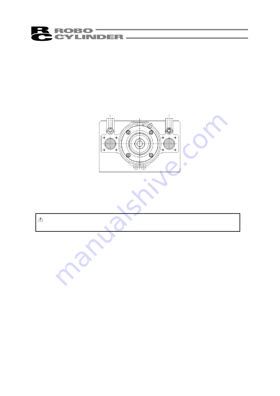
7.2 Mounting 

Surface 


 The frame should have sufficient rigidity to avoid generating vibration. 

 The surface where the actuator will be mounted should be machined or be equally level and the flatness 

tolerance between the actuator and the table should be within 0.05 mm.   

 Provide enough space around the actuator to permit maintenance work to be done.   


Caution:  The actuator has no reference plane on its base, so do not use it in applications 

where traveling precision is required. 


Summary of Contents for RCP2W

Page 1: ...IAI America Inc RCP2W ROBO Cylinder Actuator Slider Dust proof Splash proof Type Second Edition RCP2W SA16C Operating Manual ...

Page 2: ...ugh failure to do so will not result in injury It should be noted that the instructions under the Caution and Note headings may also lead to serious consequences if unheeded depending on the situation All instructions contained herein provide vital information for ensuring safety Please read the contents carefully and handle the product with due caution Please keep this operating manual in a conve...

Page 3: ...may cause electric shock or malfunction z Before supplying power to and operating the product always check the operation area of the equipment to ensure safety Supplying power to the product carelessly may cause electric shock or injury due to contact with the moving parts z Wire the product correctly by referring to the operation manual Securely connect the cables and connectors so that they will...

Page 4: ...lowing locations provide sufficient shielding measures If not the product may malfunction 1 Where large current or high magnetic field generates 2 Where welding is performed or arc discharge occurs 3 Where noise generates due to electrostatic etc 4 Where there is a risk of exposure to radiation z Do not install the product in a location subject to significant vibration or impact 4 9 m s2 or greate...

Page 5: ...rs or other guards must be provided for the moving parts of the equipment to avoid direct contact with the operators z The following conditions must be met in order to improve the straightness of the table movement and ensure the smooth movement of the ball screw and linear guides 1 Flatness of the mounting surface must be within 0 05 mm 2 The mounting surface area must be large enough to ensure t...

Page 6: ...d the information carefully to connect the cables properly 1 Do not let the cable flex at a single point 2 Do not let the cable bend kink or twist 3 Do not pull the cable with a strong force 4 Do not let the cable receive a turning force at a single point 6 Do not pinch drop a heavy object onto or cut the cable 5 When fixing the cable provide a moderate slack and do not tension it too tight Steel ...

Page 7: ...perating Environment 5 6 2 Storage Environment 5 7 Installation 6 7 1 Installing the Main Body 6 7 2 Mounting Surface 7 7 3 Installing the Load to the Slider 8 8 Connecting to the Controller 9 9 Notes on Use 10 9 1 Restrictions on Operating Condition and Installation Position 10 9 2 Precision 10 9 3 Duty 10 9 4 Moment Load 10 9 5 Splash proof Performance 11 9 6 Dust proof Performance 11 9 7 Misali...

Page 8: ......

Page 9: ...ual so that you can review the relevant sections when necessary Also peruse the operating manual for your controller for additional information regarding the actuator operation 2 Safety Precautions 2 1 Basic Operating Instructions Please do not attempt to use or operate the actuator in any manner not indicated in this manual or the controller manual Please be sure to use only the cable provided by...

Page 10: ...nts that wear out with use Unit seems to be noisy or similar impressions that do not affect machinery performance Damage resulting from improper handling by the user or lack of proper maintenance Any alterations made by other than IAI or its representatives Breakdowns caused by using controllers made by other manufacturers Any damages caused by fire and other natural disasters or accidents The war...

Page 11: ...t the actuator from the motor end with the actuator set down horizontally Front end means the side opposite the motor end z Standard Type z Cover Type Right side Left side Right side Left side Cable Slider Motor cover Side cover Motor cover Cable Slider Slider rod Front end base plate Guide rod Motor end base plate Screw cover ...

Page 12: ...e pipe to leak out and cause failures Also keep the unpacked unit in a horizontal position until installed Do not climb on top of the shipping box Do not place heavy objects on top of the shipping box 5 2 Handling the Actuator After It is Unpacked Hold the base plates when taking the actuator out of the shipping box When carrying the actuator take care not to bump it Do not exert excessive force o...

Page 13: ...from cutting oil The atmosphere is free from mist of sulfur containing cutting fluid grounding fluid etc Contact IAI for the actuator s splash proof performance against liquids other than water 6 2 Storage Environment Store the actuator in an environment meeting the same conditions specified for the installation environment If the actuator will be stored for an extended period of time take appropr...

Page 14: ...s of the actuator have through holes Use these holes when installing the actuator For installation refer to the table below and use hexagon socket head bolts of the specification appropriate for the material of the frame on which the actuator is installed Steel frame Aluminum frame M8 x 100 M8 x 110 Use of high tensile bolts conforming to ISO 10 9 or greater is recommended Recommended torque is 14...

Page 15: ...unted should be machined or be equally level and the flatness tolerance between the actuator and the table should be within 0 05 mm Provide enough space around the actuator to permit maintenance work to be done Caution The actuator has no reference plane on its base so do not use it in applications where traveling precision is required ...

Page 16: ...reamed holes on the slider when repeatability of mounting and dismounting is required When fine adjustment of the squareness is necessary use only one reamed hole to allow adjustment Diameters of tapped holes and reamed holes in slider Tapped hole diameter Tapping depth A B M8 20 mm 90 mm 115 mm Tapped hole Reamed hole ...

Page 17: ...e the cable in a movable cable duct whose bending radius is smaller than the specified dimension In applications where the cable cannot be affixed minimize the load on the cable by not allowing it to bend more than the deflection due to the self weight of the cable by using a self standing cable hose etc or by wiring the cable over a large radius Do not cut the cable or reconnect a cut cable to sh...

Page 18: ... 5 mm max 9 3 Duty During continuous operation the actuator generates frictional heat due to sliding of the pipe over the wear ring Since higher pipe temperatures reduce the clearance between the pipe and wear ring shorten the actuator life or cause other unwanted conditions use the actuator at a duty of 50 or below Duty Operating time Operating time Stopped time x 100 9 4 Moment Load The guides u...

Page 19: ...ance The electrical parts of the actuator such as its motor and encoder are designed to completely shut off dust As for the moving parts such as the sliding parts of the pipe and slider the gaps are covered with felt seals Despite the above measures however dust may still enter the pipe and slider or underneath the seals Since such dust may damage the actuator or cause other unwanted conditions de...

Page 20: ...e Tex filters are attached on the end faces of the motor case and pipe so that air pressure difference does not generate between the inside and outside or dews do not form within the actuator Take note that if these filters receive high pressure water directly or are poked with a sharp object the filters may puncture and lose their splash proofing property Filters ...

Page 21: ... month thereafter Grease may be consumed more quickly in an environment where the actuator is exposed to steam and warm water In this case it is recommended that you add grease before the scheduled timings 10 2 Visual Inspection Visually check the items specified below Actuator body Loosening of body mounting bolts etc Slider rod Lubricating condition of food grade grease scratches on pipe surface...

Page 22: ...ctuator operation washing with water and so on If necessary therefore apply grease during the inspection If the actuator had not been operated for a prolonged period of time apply grease before operating it again Applicable grease Supplier Taiyo Petroleum Gas Model Medallion FM1 antibacterial grease How to Add Grease If the actuator has a screw cover remove the cover Clean the surface of the slide...

Page 23: ... has sticky back 2 Remove smear and stain from the surface 3 Avoid label or nameplate as a marking location 1 Used to indicate the direction of actuator home 2 Used as stop positions 3 Used for position deviation check Place the marks when the actuator is stopped at home position Example of Use Contents of sticker On the slider On the base near home position Motor Motor On the slider At stop posit...

Page 24: ...912 Atlanta Office 1220 E Kenneston Circle Marrietta GA 30066 TEL 678 354 9470 FAX 678 354 9471 website www intelligentactuator com Ober der Röth 4 D 65824 Schwalbach am Taunus Germany TEL 06196 88950 FAX 06196 889524 The information contained in this document is subject to change without notice for the purpose of product improvement Copyright 2008 Apr IAI Corporation All rights reserved ...

Reviews: