Page 13
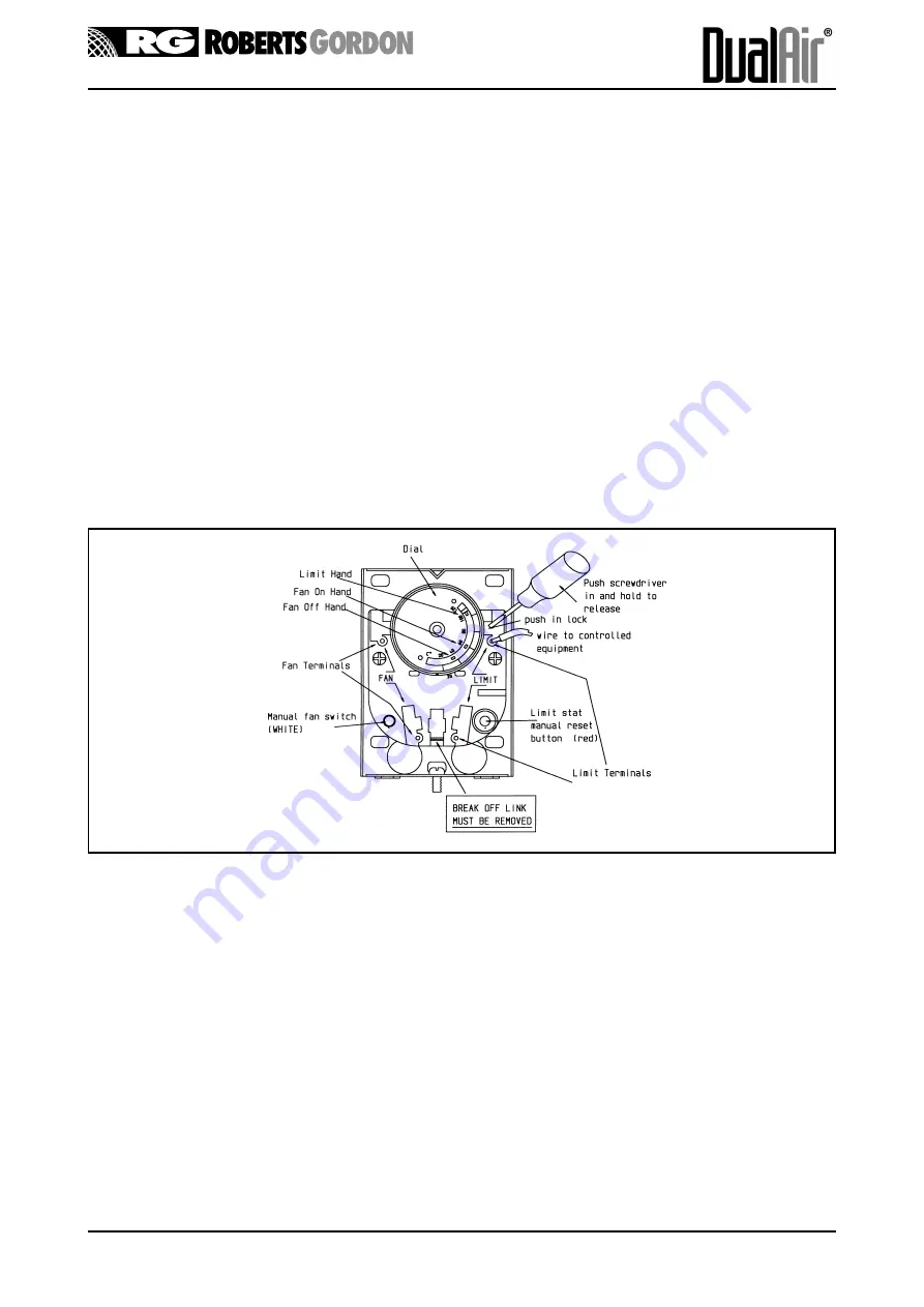
Fig. 2.2 Combination Fan/Limit Thermostat
WARNING:IT IS ESSENTIAL THAT THE BREAK OFF LINK SHOWN IS REMOVED
IN THE EVENT OF THERMOSTAT REPLACEMENT
2.3.2
Second Limit Thermostat
This is a manual reset device - see Figs. 1 .1 & 2.1.
Note: On the DualAir® models these are fitted so that the sensing element is on the lower rear of the
heat exchanger in the same way as for the standard CUHD unit heater. The operating head of the
thermostat is located on the side panel of the CUHD heater section.
To reset this thermostat:
a)
Remove the screw on cover of the thermostat .
b)
Push in the button in the centre of the thermostat. Note: the heat exchanger must be cooled to
allow this to happen.
c)
Replace the cover.
Summary of Contents for Dualair DA260G Series
Page 2: ...Details of condense drain for cooling coil ...
Page 9: ...Page 7 Fig 2 2 DualAir 380 Module Dimensions FRONT VIEW REAR VIEW SIDE VIEW ...
Page 34: ...Page 32 Fig 5 2 Wiring for DualAir Units On Off Burner 24v Controls ...
Page 35: ...Page 33 Fig 5 3 Wiring for DualAir Units Hi Low Burner 230v Controls ...
Page 36: ...Page 34 Fig 5 4 Wiring for DualAir Units Hi Low Burner 24v Controls ...
Page 37: ...Page 35 Fig 5 6 Wiring for DualAir Units BMS Burner Modulation 230v Controls ...
Page 38: ...Page 36 Fig 5 7 Wiring for DualAir Units BMS Burner Modulation 24v Controls ...
Page 39: ...Page 37 Fig 5 7 Wiring for DualAir Units Full Burner Modulation 230v Controls ...
Page 40: ...Page 38 Fig 5 8 Wiring for DualAir Units Full Burner Modulation 24v Controls ...
Page 41: ......
Page 42: ......
Page 43: ......
Page 44: ......
Page 45: ......
Page 46: ......
Page 47: ......
Page 48: ......
Page 49: ......
Page 50: ......


