Reference: Appliance Specifications | 67
Interceptor 9800 specifications
This table summarizes the LEDs and buttons on the front of the Interceptor 9800 appliance.
Back panel, ports, and status lights
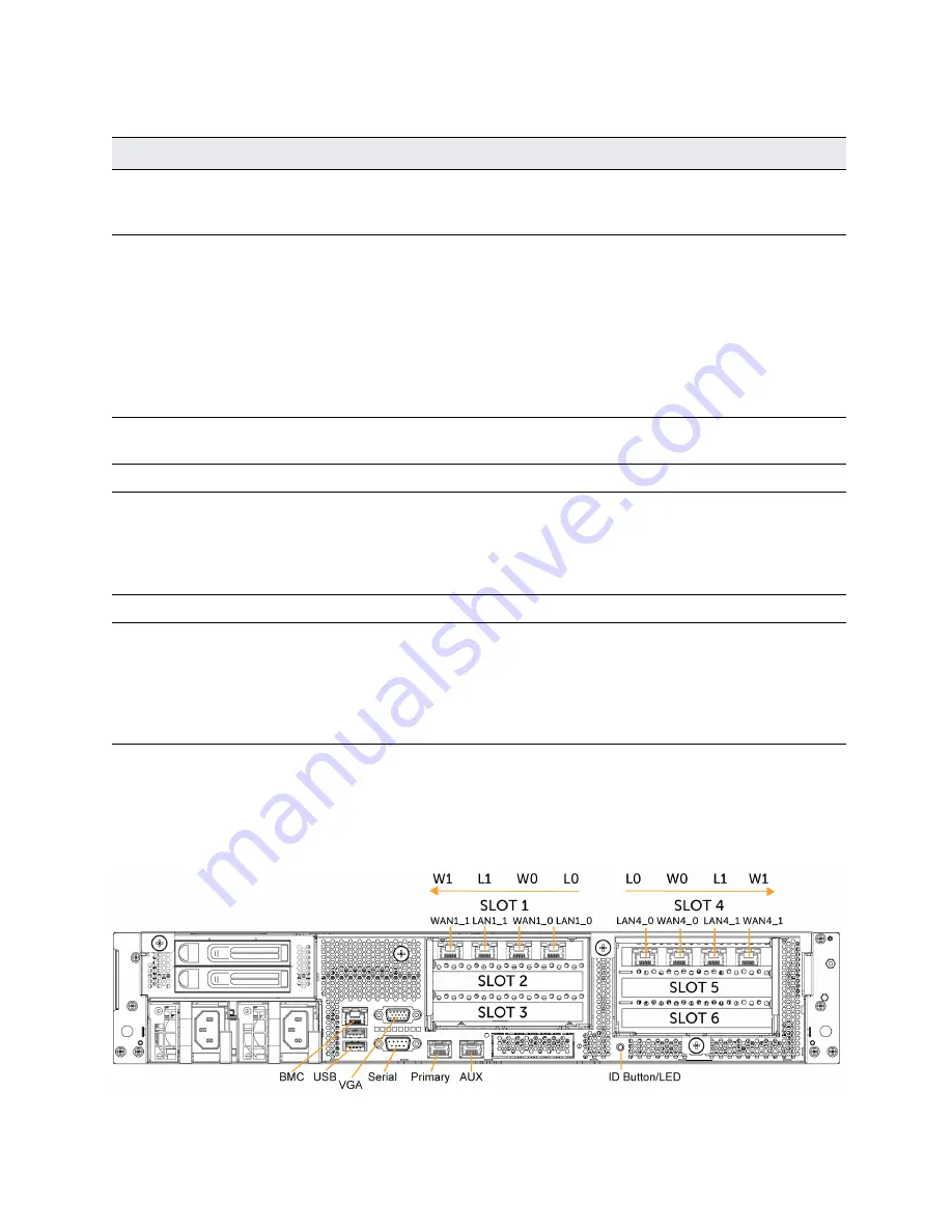
This figure illustrates the back of the appliance, including the ports.
Figure A-8. IC 9800 back panel
Reference
LED/button
Description
1
Power On/Off Button and
Integrated LED
On = Green (System is turned on.)
Sleep State = Green (System is in S1 or S3 sleep state.)
Off = No Light (Power is off.)
2
IPMI Warning LED
The IPMI Warning LED shows the current health of the server
system.
Normal = Green (No failures)
Degraded/Warning = Amber (Indicates fan failure, high
temperature, over voltage, or power supply failure.)
Critical = Blinking Amber and Green (Indicates a problem that
needs attention, such as optimization service down, no license, or
in_path is not enabled for optimization service.)
3
ID LED
On = Blue (System identified remotely on the server.)
Off = Off (System not identified.)
4
Reset Button
Press to reboot the appliance.
5
System ID Button
Press the system ID button when the system AC (Alternating
Current) is on. The system ID LED indicates the system is identified
with a blue light. Users from a remote site can activate the ID LED
by inputting commands in IPMI. For details, contact Riverbed
Support at
https://support.riverbed.com
.
6, 7
USB Ports v2.0
8
HDD/SSD LEDs
Activity LED (lower light)
Link = Green (Drive present, with no activity.)
Activity = Blinks Green (Drive present, with activity.)
Status LED (upper light)
Failed Disk = Solid Red


