22
PUB. NO. FASTRAXC FEBRUARY 2008
FASTRAX
™
VIRTUAL VISION INSTALLATION
NOTE: Virtual Vision is standard on Freezer / Cooler doors
provided with the Insulmax curtain. There will be a
motion sensor mounted on each side of the door,
as well as 2 red LED light bars on each side of the
opening on both sides. The motion sensors will
detect motion on the opposite side of the curtain to
warn oncoming traffic of a possible pedestrian or
forklift on the opposite side.
1.
If door is equipped with Thermal Air Seal Step Down
Transformer junction box, plug in Virtual Vision cable. If
not, there will be a separate junction box strictly for the
Virtual Vision.
2.
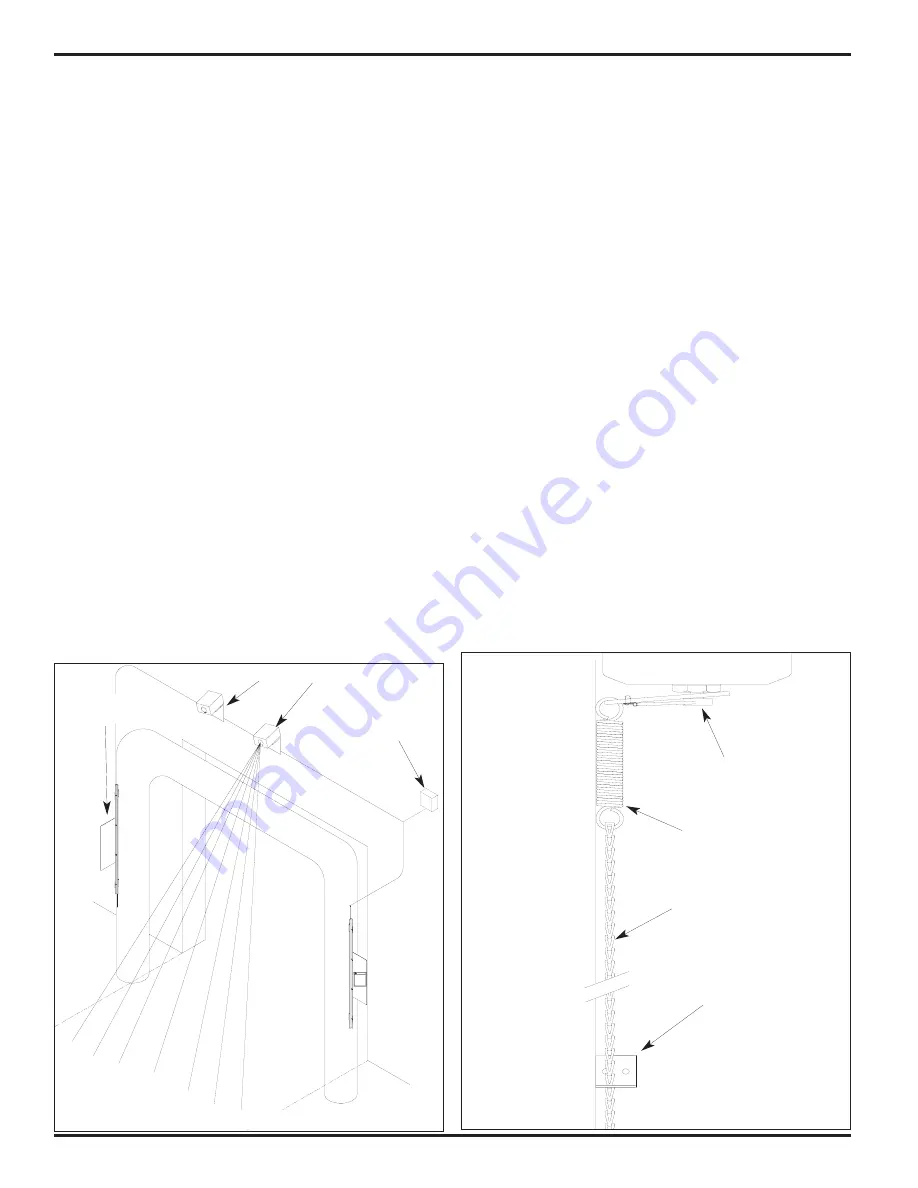
Virtual Vision light bar assemblies should be located on
each side of the doorway and in clear view of oncoming
traffic. They should be installed approximately 3' off the
floor, adjacent to the doorway (e.g. goal posts or wall) and
in a location that is protected from potential impact
damage,
Figure 39.
3.
Motion sensors can be installed above the opening on
Radial doors or off to the side if Vertical, 45° Tilt, High or
Standard lift.
4.
Sensors should be programmed for a 2 second hold time
and bi-directional detection.
5.
Direct sensors so they DO NOT extend beyond the width
of the door.
6.
Plug cables together and wire into control box.
7.
To avoid cross talk when changing the settings on the
Virtual Vision or activation sensors when using the remote
controls, Rite-Hite offers the following three options:
a)
The BEA remote control allows you to set a unique
security code for each sensor. That way, you would enter
the code for the sensor you are interested in changing,
and it will only change the settings for that sensor. To
accomplish this, temporarily disconnect the activation
sensor(s) from its power supply (at the I-COMM), use the
remote to set a security code (e.g. "1111") for the Virtual
Vision sensor(s), then power up all sensors. The
activation sensor will have the default security code
"0000" for its settings, and the Virtual Vision sensor will
have its new security code when changing its settings
(use unlock/lock sequence). There should be no cross-talk
with the remote's instructions when using this approach.
Make sure to record these values for future reference.
b)
If you do not wish to use security code settings, you can
simply power down one unit (at the I-COMM) while setting
the other unit, and then do the same thing with the other
unit. This is similar to option "a", although if you want to
make subsequent changes to the settings, you would
need to go through the power down procedure again.
c)
If you do not wish to power down the units or use security
settings, you can physically cover one of the units while
programming the other unit. Any opaque material (e.g.
cardboard) should work. However, with units typically
mounted high above the opening, this may be difficult.
BRAKE RELEASE INSTALLATION
1.
If door is equipped with the brake release option, see
Figure 40.
2.
Remove brake handle and attach brake release bracket to
the bottom of the brake.
3.
Attach spring to the bracket and chain to the spring.
4.
Install wall mount bracket to wall, so that it will hold chain
in place, to release brake. Trim excess chain as required.
VIRTUAL VISION
Do Not Enter
On Red Light
Personnel Or Equipment
May Be Present On The
Other Side Of The Door
WARNING
FIGURE 39 - VIRTUAL VISION
FIGURE 40 - BRAKE RELEASE
Pull Chain
Wall Mount Bracket
Brake
Spring
Brake Release Bracket
Virtual Vision Sensor
Virtual Vision
Junction Box
Opposite Side
Virtual Vision Lite
Bar Assembly
Motion Sensor
Summary of Contents for FASTRAX
Page 13: ...PUB NO FASTRAXC FEBRUARY 2008 13 FASTRAX i COMM LOGIC CHART FIGURE 22 LOGIC CHART...
Page 32: ...32 PUB NO FASTRAXC FEBRUARY 2008 FASTRAX VIRTUAL VISION ELECTRICAL WIRING...
Page 36: ...36 PUB NO FASTRAXC FEBRUARY 2008 FASTRAX RADIAL ARCHITECTURAL DRAWING D O O R SYSTEM...
Page 37: ...PUB NO FASTRAXC FEBRUARY 2008 37 FASTRAX VERTICAL ARCHITECTURAL DRAWING D O O R SYSTEM...
Page 38: ...38 PUB NO FASTRAXC FEBRUARY 2008 FASTRAX STANDARD LIFT ARCHITECTURAL DRAWING D O O R SYSTEM...
Page 39: ...PUB NO FASTRAXC FEBRUARY 2008 39 FASTRAX HIGH LIFT ARCHITECTURAL DRAWING D O O R SYSTEM...
Page 40: ...40 PUB NO FASTRAXC FEBRUARY 2008 FASTRAX 45 TILT ARCHITECTURAL DRAWING D O O R SYSTEM...
Page 41: ...PUB NO FASTRAXC FEBRUARY 2008 41 FASTRAX FR VERTICAL ARCHITECTURAL DRAWING D O O R SYSTEM...
Page 42: ...42 PUB NO FASTRAXC FEBRUARY 2008 FASTRAX FR STANDARD ARCHITECTURAL DRAWING D O O R SYSTEM...
Page 43: ...PUB NO FASTRAXC FEBRUARY 2008 43 FASTRAX FR HIGH LIFT ARCHITECTURAL DRAWING D O O R SYSTEM...
Page 44: ...44 PUB NO FASTRAXC FEBRUARY 2008 FASTRAX FR 45 TILT ARCHITECTURAL DRAWING D O O R SYSTEM...


