18
ADJUSTMENTS
Lower Guides -
continued
:
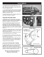
2. Set both side bearing guides to within 1/16” of the
saw blade - about the same thickness of a business
card. Do not set the bearing guides too close, or touch
the sides of the blade, as this will adversely affect the
life of the saw blade and bearings.
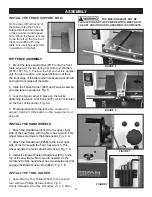
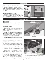
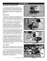
3. First, loosen the front Locking Knobs (A,
Fig 26).
To move the guides towards or away from the
blade, use the Locking Knobs as handles to slide
the bearings in place. Once set, secure the Locking
Knobs.
4. Adjust the rear bearing guide to be just clear of
the back of the saw blade. Loosen the rear guide’s
Locking Knob (A,
Fig 27)
, and move the rear guide
towards the blade by turning the lower, front micro-
adjustment Knob (B,
Fig 27)
. When the correct
adjustment is made, lock the guide in place by
tightening the Locking Knob (A).
NOTE:
If the rear guide will not adjust close to the
rear of the blade (possible issue with thin blades), the
position of the blade on the wheel can be adjusted,
or the lower Plate can be moved. There is a second
position hole in the plate for the Hex Bolt. Unscrew
the bolt and reposition it thru the plate’s other hole.
This will re-adjust the guide’s travel distance.
ADJUSTING THE BLADE GUIDES - continued
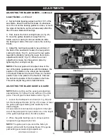
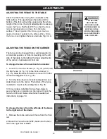
FIGURE 29
FIGURE 28
Approximately
1/4”
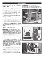
ADJUSTING THE BLADE GUIDE & GUARD
NOTE:
Before cutting, set the upper guide bearings
approximately 1/4” above the top surface of the work
piece. This will give the best blade control. Fig. 28.
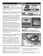
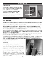
1. Loosen the Guidepost Lock Knob (A, Fig. 30) and
turn the Guidepost Handle (B, Fig. 29) to raise or lower
the guide post/upper blade guide assembly to the
desired height.
A measurement scale has been supplied on the right
side of the guide post for quick reference on the height
of the guide bearings above the table surface.
2. When the guide bearings are in proper position,
re-tighten the guidepost lock knob.
NOTE:
The guide post is pre-set at the factory to
aligned vertical with the bandsaw blade. If the guide
post setting ever needs slight adjustment:
FIGURE 30
CONTINUED ON PAGE 19
FIGURE 26
FIGURE 27
A
B
A
C
C
A
1/16”
A
F
Summary of Contents for 10-324TG
Page 43: ...43 OPERATION...

