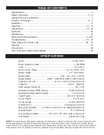
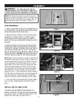
Rikon Power Tools 10-324TG Operator'S Manual Download Page 4

4

SAFETY INSTRUCTIONS


16.  

NEVER LEAVE A RUNNING TOOL UNATTENDED. 

Turn the power switch to the “OFF” position. 

DO NOT 

leave the tool until it has come to a complete stop.

17.  

DO NOT STAND ON A TOOL.

 Serious injury could 

result if the tool tips over, or you accidentally contact the 

tool.

18.  

DO NOT

 store anything above or near the tool where 

anyone might try to stand on the tool to reach it.

19.  

MAINTAIN YOUR BALANCE. DO NOT

 extend 

yourself over the tool. Wear oil resistant rubber soled 

shoes. Keep floor clear of debris, grease, and wax.

20.  

MAINTAIN TOOLS WITH CARE.

 Always keep tools 

clean and in good working order. Keep all blades and tool 

bits sharp, dress grinding wheels and change other 

abrasive accessories when worn. 

21.  

EACH AND EVERY TIME, CHECK FOR DAMAGED 

PARTS PRIOR TO USING THE TOOL.

 Carefully check 

all guards to see that they operate properly, are not dam-

aged, and perform their intended functions. Check for 

alignment, binding or breaking of moving parts. A guard 

or other part that is damaged should be immediately 

repaired or replaced.

22.  

DO NOT OPERATE TOOL WHILE TIRED, OR 

UNDER THE INFLUENCE OF DRUGS, MEDICATION 

OR ALCOHOL.

23.  

SECURE ALL WORK. 

Use clamps or jigs to secure 

the work piece. This is safer than attempting to hold the 

work piece with your hands.

24.  

STAY ALERT, WATCH WHAT YOU ARE DOING, 

AND USE COMMON SENSE WHEN OPERATING A 

POWER TOOL.


A moment of inattention while operating power tools may 

result in serious personal injury.
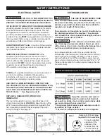
26.  

USE A PROPER EXTENSION CORD IN GOOD 

CONDITION.

 When using an extension cord, be sure to 

use one heavy enough to carry the current your product 

will draw. The table on the following page shows the cor-

rect size to use depending on cord length and nameplate 

amperage rating. If in doubt, use the next heavier gauge. 

The smaller the gauge number, the larger diameter of the 

extension cord. If in doubt of the proper size of an exten-

sion cord, use a shorter and thicker cord. An undersized 

cord will cause a drop in line voltage resulting in a loss of 

power and overheating. 

USE ONLY A 3-WIRE EXTENSION CORD THAT HAS 

A 3-PRONG GROUNDING PLUG AND A 3-POLE 

RECEPTACLE THAT ACCEPTS THE TOOL’S PLUG.

27. 

ADDITIONAL INFORMATION

 regarding the safe and 

proper operation of this product is available from:

• 

Power Tool Institute

         1300 Summer Avenue

         Cleveland, OH 44115-2851

         www.powertoolinstitute.org

• 

National Safety Council

         1121 Spring Lake Drive

         Itasca, IL 60143-3201

         www.nsc.org

• 

American National Standards Institute

         25 West 43rd Street, 4th Floor

         New York, NY 10036

         www.ansi.org

• 

ANSI 01.1 Safety Requirements for

         Woodworking Machines and the

         U.S. Department of Labor regulations

         www.osha.gov

28. 

SAVE THESE INSTRUCTIONS.

 Refer to them 

frequently and use them to instruct others.

25.  

ALWAYS WEAR A DUST MASK TO PREVENT 

INHALING DANGEROUS DUST OR AIRBORNE 

PARTICLES

, including wood dust, crystalline silica dust 

and asbestos dust. Direct particles away from face and 

body. Always operate tool in well ventilated area and 

provide for proper dust removal. Use dust collection 

system wherever possible. Exposure to the dust may 

cause serious and permanent respiratory or other injury, 

including silicosis (a serious lung disease), cancer, and 

death. Avoid breathing the dust, and avoid prolonged 

contact with dust. Allowing dust to get into your mouth 

or eyes, or lay on your skin may promote absorption of 

harmful material. Always use properly fitting NIOSH/OSHA 

approved respiratory protection appropriate for the dust 

exposure, and wash exposed areas with soap and water.

12.  

KEEP PROTECTIVE GUARDS IN PLACE AND IN 

WORKING ORDER.

13.  

AVOID ACCIDENTAL STARTING. 

Make sure that 

the power switch is in the “OFF” position before plugging 

in the power cord to the electrical receptacle.

14.  

REMOVE ALL MAINTENANCE TOOLS

 from the 

immediate area prior to turning “ON” the machine. 

15.

  USE ONLY RECOMMENDED ACCESSORIES. 

Use 

of incorrect or improper accessories could cause serious 

injury to the operator and cause damage to the tool. If in 

doubt, check the instruction manual that comes with that 

particular accessory.

Summary of Contents for 10-324TG

Page 1: ...your manual for future reference The serial number can be found on the specification label on the rear of your machine Serial Number _________________________ Date of purchase ________________________...

Page 2: ...ation 22 Maintenance 23 Electricals Wiring Diagram 5 23 Troubleshooting 24 27 Parts Diagrams Parts Lists 28 41 Warranty 41 Accessories 42 How To Guide for all Band Saw Blades 43 Motor 1 5 HP TEFC Moto...

Page 3: ...trical receptacle The 3rd prong is used to ground the tool and provide protection against accidental electric shock DO NOT remove the 3rd prong See Grounding Instructions on the following pages 4 AVOI...

Page 4: ...er cord An undersized cord will cause a drop in line voltage resulting in a loss of power and overheating USE ONLY A 3 WIRE EXTENSION CORD THAT HAS A 3 PRONG GROUNDING PLUG AND A 3 POLE RECEPTACLE THA...

Page 5: ...nel if you do not completely understand the grounding instructions or if you are not sure the tool is properly grounded when installing or replacing a plug USE ONLY A 3 WIRE EXTENSION CORD THAT HAS TH...

Page 6: ...ming jammed in the table insert or lower blade guides 13 Always allow the bandsaw blade to stop before removing scrap pieces from the table 14 Do not remove jammed pieces from the saw until the machin...

Page 7: ...Blade Guides M Table with Round Blade Insert N Miter Gauge T Slots O Lower Blade Guides and Guard P Drive Belt Tension Hand Wheel Q Storage Shelf R 4 Dust Port S Table Tilt Hand Wheel T Table Locking...

Page 8: ...r any possible insurance claims 3 With the help of another person carefully lift the Bandsaw from the packaging and place it on a level floor 4 Clean all rust protected surfaces with ordinary house ho...

Page 9: ...ide of the column so that the table assembly is not compromised DO NOT install casters onto the stand s legs as this will make the bandsaw unstable Use a universal mobile base available separately fro...

Page 10: ...e on top of the stand Securely fasten it to the stand with the four bolts B If alone lay the bandsaw down on its column onto 4 x4 wood blocks Then also lay the stand on its side on wood blocks to matc...

Page 11: ...aw blade This will provide a true cut when ripping stock Set a thin metal ruler against the side of the saw blade Make sure that it is not touching the saw s teeth which can angle the ruler Measure th...

Page 12: ...RE 6 INSTALL THE HAND WHEELS 1 Attach the Handwheel 31D to the upper right side of the saw frame with the 5mm hex wrench This wheel raises and lowers the blade guard Fig 7 A 3 Attach the Handwheel 26E...

Page 13: ...r scale that is cast into the trunnion bracket Support 17B C to find the desired angle 3 Retighten the locking handle to secure the table FIGURE 11 B A FIGURE 10 C SETTING THE TABLE SQUARE TO THE SAW...

Page 14: ...e factory and any changes made to this wheel should be after thorough reading and understanding of the instructions Failure to do so could damage the machine FIGURE 14 FIGURE 15 ADJUSTMENTS FIGURE 13...

Page 15: ...d up the saw blade should deflect about 1 4 when pressed with a finger to the side of the blade See page 16 for information on Adjusting the Blade Tension Stop for tensioning blades that are welded a...

Page 16: ...moving the quick release lever back to the ON position Fig 20 and check the blade tracking The blade should run in the center of the wheels Refer to Tracking the Saw Blade on page 14 for more details...

Page 17: ...the saw blade about the same thickness of a business card Fig 22 Do not set the bearing guides too close or touching the sides of the blade as this will adversely affect the life of the blade and bea...

Page 18: ...he blade on the wheel can be adjusted or the lower Plate can be moved There is a second position hole in the plate for the Hex Bolt Unscrew the bolt and reposition it thru the plate s other hole This...

Page 19: ...e This will allow the guide post to be shifted angled a bit left or right to correct any positioning issues 5 There are also four Set Screws Fig 31 set in the rear of the guide bracket near the corner...

Page 20: ...are and front rail To change the fence from vertical to horizontal 1 Loosen the two Hex Screws A Fig 35 which hold the Rip Fence B Fig 35 to the Fence Carrier C Fig 35 Slide the fence forward to remov...

Page 21: ...lade type is necessary for clean effective cutting action in these materials CUTTING SPEEDS TENSION PULLEY V BELT PULLEY MOTOR LOWER BANDSAW WHEEL 1 5 4 2 3 POS 1 TO 3 TO 5 1 445 FT MIN 440 M MIN POS...

Page 22: ...blade will not cut correctly especially when straight cutting and causes excess pressure to be applied on the rear guide bearings Select the right blade for the job depending on the thickness of the w...

Page 23: ...he white switch wire lead Tie the brown and black motor leads together with spare wire nut supplied Disregard the wires that lead to the capacitor For 230V wiring DISCONNECT the wires leading to the P...

Page 24: ...properly adjusted 3 Inferior blade REMEDY Check the cable for breakage Contact your local dealer for repair parts Switch off the motor tighten the quick release lever or blade tension handwheel Open t...

Page 25: ...ws with a hex L wrench counter clockwise to lower the insert If the insert is sitting below the table turn the micro screws clockwise to raise the insert level with the table Caution Having the insert...

Page 26: ...oid damaging the machine If the blade is not running true or it is not running on center of the lower wheel but is correct on the upper wheel then an adjustment to the wheel hub on the rear of the ban...

Page 27: ...nsure that it has been welded correctly so that the blade s back is in proper alignment flat if it is laid down on a table surface If the blade is welded true then adjustment to the wheel hub on the r...

Page 28: ...nt Parts For Parts under Warranty the Serial Number of your machine is required PARTS DIAGRAM 15 16 17 18 19 20 21 22 26 25 27 28 29 23 30 34 33 35 36 32 31 37 38 39 41 40 42 43 44 45 46 1 47 48 49 11...

Page 29: ...34A 35A 36A 37A 38A 39A 40A 41A 42A 43A 44A 45A 46A 47A 48A 49A 50A 51A 52A 1 JL28010003 001S 1 JMBS1404011000 117U 1 JL27010005 1 M4GB6170B 1 WSH4GB862D2B 1 JMBS1404010200 076U 1 JMBS1404010400 1 M4X...

Page 30: ...17 23 21 22 26 30 29 28 27 31 25 24 11 10 9 8 7 3 1 6 5 32 TABLE ASSEMBLY SHEET B NOTE Please reference the Manufacturer s Part Number when calling for Replacement Parts For Parts under Warranty the...

Page 31: ...29B 30B 31B 32B 1 M6X4GB77B 1 JL26050008A 001S 1 JMBS1404030100A 001G 1 JMBS1404030002 1 WSH4GB96D1B 1 M4X10GB818B 1 M8GB6170B 1 M8X25GB5783B 1 WSH8GB97D1B 1 WSH8GB93B 1 M8X20GB70D2B 1 PIN3X18GB879B...

Page 32: ...32 PARTS DIAGRAM BLADE TENSION TRACKING ASSEMBLY SHEET C 1 2 3 4 5 6 7 8 9 10 11 12 13 14 15 16 17 18 19 20 21 22 23 24 26 25...

Page 33: ...13C 14C 15C 16C 17C 18C 19C 20C 21C 22C 23C 24C 25C 26C 1 JL21025000A001S 1 JL28032000A 1 JL28030003 1 WSH12GB97D1Z 1 M6X12GB70D1Z 1 WSH6GB5287Z 1 JL28030008 1 JL28031000 1 JL28030001 1 JL28030010 1...

Page 34: ...28 29 33 34 35 36 25 21 NOTE Please reference the Manufacturer s Part Number when calling for Replacement Parts For Parts under Warranty the Serial Number of your machine is required BLADE GUARD TOP...

Page 35: ...r 1D 2D 3D 4D 5D 6D 7D 8D 9D 10D 11D 12D 13D 14D 15D 16D 17D 18D 19D 20D 21D 22D 23D 24D 25D 26D 27D 28D 29D 30D 31D 32D 33D 34D 35D 36D DESCRIPTION 1 JL82240011 001S 1 M6X16GB5783B 1 WSH6GB96B 1 JL27...

Page 36: ...36 PARTS DIAGRAM 4 3 2 5 6 7 8 13 12 14 15 16 11 10 9 17 18 19 20 21 22 18 19 20 23 25 26 27 28 29 30 24 1 MOTOR WHEEL ASSEMBLY SHEET E...

Page 37: ...k handwheel Set screw M8x35 Set screw M5x8 Set collar Crank 1E 2E 3E 4E 5E 6E 7E 8E 9E 10E 11E 12E 13E 14E 15E 16E 17E 18E 19E 20E 21E 22E 23E 24E 25E 26E 27E 28E 29E 30E DESCRIPTION 1 JL28020001C 2 Y...

Page 38: ...e rail Re saw bar Screw Support shaft Nut M8 Flat washer Flat washer 1 1 1 1 1 1 1 2 2 2 1 1 1 2 4 4 1 1 JMBS1404060001 1 JL93010018 1 JMBS1403061002 1 KTSB 1 A M6X50 1 JMBS1404060003 1 JMBS1601060003...

Page 39: ...ate Cross recessed pan head screw M4X8 Long sleeve Hex socket set screw with flat end M8X10 Upper guide support Upper guide shaft Front and rear positioning support plate Spring washer Long bolt Hex s...

Page 40: ...ad screw M4X5 Washer Lower guide Hex socket set screw M6X6 Rear adjusting spindle Lower guide shaft Base plate Washer Washer 1 1 1 1 2 1 2 1 3 3 2 1 1 1 1 1 1 2 2 3 1 3 2 1 1 1 1 1 KTSB 1 A M6X50 1 JL...

Page 41: ...PTION QTY PART NO 1I 2I 3I 4I 5I 6I 7I 8I Hex flat head bolt M6x50 to attach saw to stand Upper frame Hex nut with flange to attach saw to stand Shelf Carriage bolt M6x16 Leg Hex nut M6 Flat washer 4...

Page 42: ...the slot width so debris or thin cut wood strips will not catch or fall into the thin slot Ideal for use when cutting small pieces on the bandsaw for inlay shims puzzles etc BAND SAW BLADES For a vari...

Page 43: ...43 OPERATION...

Page 44: ...www rikontools com 10 324TGM1 10 324TG For more information 16 Progress Road Billerica MA 01821 877 884 5167 978 528 5380 techsupport rikontools com LINK TO RIKON WEBSITE...

Reviews: