background image


20


9.PRODUCT SPECIFICATIONS 

 
9-1.Standard specifications 


Model 

GD-F4A-SC-A 

Detection principle 

Galvanic cell method 

Detectable gas 

O

2


Detection method 

Suction method (with flow passage) 

Suction flow 

1.0±0.3L/min   

Transmission method 

Analog transmission 

Transmission specification 

4-20mADC 

Transmission cable 

CVVS 1.25mm

2

・2-core or equivalent 

Transmission distance 

Up to 2km with CVVS 1.25mm

2


(up to 250m between the detector head and Zener barrier) 

Power supply 

24VDC (supplied from indicator/alarm unit) 

Zener barrier 

MTL7728ac//MTL7728- 
ZB-1A/ZB-1A+/ZB-1A- 
ZB-4A/ZB-4A+/ZB-4A- 

Cabling port 

Cable gland (Applicable cable O.D.φ8 -  φ11mm) 

Piping port 

Rc1/8 (with half union for O.Dφ8-1t) 

Operating temperature 

-10 - +40℃  (non-rapidly-vary) 

Operating humidity 

Less than 90%RH (non-condensing) 

Structure 

Wall mounting type/mountable to pipe size 2B<50A> 

Explosion-proof structure 

Intrinsically safe structure(by using zener barrier) 

Explosion-proof grade 

Ex ia  ⅡC T4 X 

Outer dimension 

Approx. 140(W)×175(H)×95(D)mm 

Weight 

General spec.:approx.1.7kg 
Stainless steel spec.:approx.2.0kg 

Color 

Munsel 2.5Y9/2 half tone 


9-2.Standard accessories 

・Operating manual 
・Sensor 


9-3.Optional accessories 

・U-bolt (for nominal diameter 2B) 
・Zener barrier (MTL7728ac) 


Summary of Contents for GD-F4A-SC-A

Page 1: ...Oxygen Gas Detector Head GD F4A SC A Operating Manual PT2 152 PT2E 2510...

Page 2: ...tector head 2 Alarm level for gas alarm instrument shall be set within the performance of the instrument Our standard alarm level is 18 by volume for the prevention of oxygen deficiency 3 This is not...

Page 3: ...up 12 How to start the detector head 12 How to exit 12 MAINTENANCE Maintenance intervals and items 13 Calibration Required kit and tools for calibration 14 Performing a zero adjustment 14 Performing...

Page 4: ...or alarm unit to show oxygen content Read the operating manual for indicator alarm unit as well as this manual This unit is designed as drip proof construction for outdoor installation Also it can be...

Page 5: ...nterval Do not change or remodel the circuit structure of this unit Do not disassemble the sensor since there is a electrolyte inside If your finger touches the electrolyte wash your finger away with...

Page 6: ......

Page 7: ...l strip 2 Relayed terminal for input output signal use to the signal converter 4mA adjusting hole VR hole to adjust 4 mA of 4 20mA output factory set SPAN adjusting hole VR hole to adjust SPAN ZERO ad...

Page 8: ...rformance division and group Performance division ia Group C 3 Relations between allowable inductance Lo and allowable capacitance Co of intrinsic safety circuit and external wiring inductance Lw and...

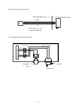
Page 9: ...inside detector head Detector head Indicator alarm unit Non hazardous area Non hazardous area CVVS 1 25mm2 2 core or equivalent MAX 2km 4 20mA Signal converter Sensor lead wire Terminal 4 20mA Cable...

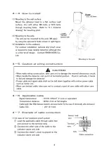
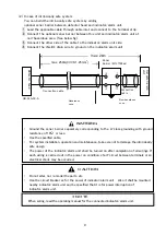
Page 10: ...e to get direct rays of the sun Places closed to high temperature and or emission of electromagnetic wave Place with vibration or shocks Place where the mounting part is weak and it is easy to come ou...

Page 11: ......

Page 12: ...ator alarm unit and be specified that it is for power interruption of indicator alarm unit Ground the zener barrier separately corresponding to the A class grounding with ground resistance of 10 or le...

Page 13: ...se 8 O D 1t copper pipe and so on for piping Carry out piping works as straight as possible Excessively high load may cause burden on the suction pump shortening the effective life of the pump When be...

Page 14: ...en the pump cannot be used If the sample gas pressure would fluctuate use the constant flow rate control valve to keep the constant flow rate Exhaust the sampled gas to open air in principle When make...

Page 15: ...the gas flow be sampled to this unit by turning on the pump switch etc Adjust the flowrate to lead sampled gas to 1 0L 0 3mL min Be sure to perform gas calibration at the time of new installation Corr...

Page 16: ...is also necessary to carry out gas calibration at least every 6 months The law in Japan sets forth that the unit must issue an alarm during the circuit maintenance related to alarm while providing no...

Page 17: ...bration and confirm that the oxygen reading returns to 20 9vol Return disconnected piping to where they were completion of zero adjustment Performing a span adjustment Plug the ammeter to terminal no...

Page 18: ...gen sensor has an enough life span However the actual life is depending on the operating conditions Then replace the sensor once a year as the tentative deadline for the replacement cycle NOTE Output...

Page 19: ......

Page 20: ...temperature 5 10 Environment of low oxygen content Put a sensor into the container and seal off the container List of recommendable spare parts for regular replacement No Name of parts Inspection fre...

Page 21: ...head is relocated select a new place in accordance with 4 2 Precautions for installation points and 4 4 How to install For information on wiring work see 4 5 Caution at wiring construction The unpowe...

Page 22: ...r authorized agent or RIKEN KEIKI Before it is thought to be a trouble Check the wirings around the related instruments as well as this detector head It may be caused by improper operation Re check th...

Page 23: ...barrier MTL7728ac MTL7728 MTL7728 ZB 1A ZB 1A ZB 1A ZB 4A ZB 4A ZB 4A Cabling port Cable gland Applicable cable O D 8 11mm Piping port Rc1 8 with half union for O D 8 1 Operating temperature 10 40 non...

Page 24: ......

Page 25: ...r Safety retainer for explosion protection by limiting the energy of electric current within a non ignition level CVVS This is a kind of connecting cable between indicator alarm unit and oxygen detect...

Page 26: ...Manual Log Rev Amendment Issue data 0 First issue 2018 2 9...

Reviews: