9
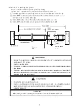
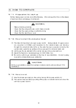
(2) In case of intrinsically safe system
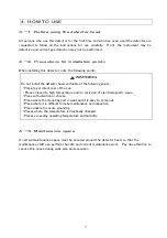
You can build the intrinsically safe system by adding
optional zener barrier between detector head and indicator/alarm unit.
①
Lead the applicable cable through cable inlet and connect to the terminal strip.
② Connect the optional zener barrier between this unit and indicator/alarm unit at
non-hazardous area. (See below fig.)
③ Connect the other side of the cable to the indicator/alarm unit side.
④ Connect the shield
’
s drain wire to ground on the indicator/alarm unit.
・
Do not alter, nor remodel the parts, etc.
・
Use the circuit breaker as for the power of indicator/alarm unit. Also it shall be mounted
nearby indicator/alarm unit and be specified that it is for power interruption of
indicator/alarm unit.
・
Ground the zener barrier separately corresponding to the A-class grounding with ground
resistance of 10Ω or less.
・
Use the specified cable.
・
For system installation, operation and maintenance, take care not to damage the intrinsically
safe design.
・
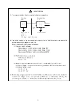
The power of the indicator/alarm unit shall be turned on after completion of all wirings. If
each wiring is carried out in the power on condition, short-circuit between terminals or an
electrical shock may be occurred.
* NOTE
When wiring, read the operating manual for the connected indicator/alarm unit.
WARNING
CAUTION
!
GD-F4A-SC-A
1
3
2
4
D
e
t
e
c
t
o
r
h
e
a
d
I
n
d
i
c
a
t
o
r
/
a
l
a
r
m
u
n
i
t
Zener
barrier
(
MTL7728ac
)
max. 2km
max. 250m(CVVS 1.25mm
2
)
Hazardous
zone
Non-hazardous
zone
Connection cable
Connection
cable
Summary of Contents for GD-F4A-SC-A
Page 1: ...Oxygen Gas Detector Head GD F4A SC A Operating Manual PT2 152 PT2E 2510...
Page 6: ......
Page 11: ......
Page 19: ......
Page 24: ......
Page 26: ...Manual Log Rev Amendment Issue data 0 First issue 2018 2 9...


