15
20098582
GB
Installation
A burner's exact delivery can only be determined by weighing.
Suck the fuel from a recipient mounted on a weighing machine,
or attach hoses to the nozzles and weigh the fuel that flows out.
A liter counter can be applied to the pump’s suction line if a sin-
gle-pipe supply system has been provided.
NOTE:
nozzle manufacturers discourage opening of the nozzle to clean
its internal parts and especially its calibrated hole. The filter, on
the other hand, may be cleaned or replaced as required. Grip the
nozzle on its hexagonal part when handling.
5.7.1
Choice of nozzle
The nozzle must be chosen from among those listed in Tab. I.
Use nozzles with atomization angles of 60° and, if possible, at a
pressure of 12 bar.
Tab. I
(1)
Light oil: density 0,84 kg/dm
3
- viscosity 4,2 cSt/20°C - temperature
10°C.
Example:
Boiler output = 230 kW - efficiency 90%
Output required by the burner = 230 : 0.9 = 255 kW (21.5 kg/h);
therefore 1 nozzle - 5,00 GPH - 60° - 12 bar is required.
NOTE:
other information regarding nozzles may be found in Tab. H on
page 14.
5.7.2
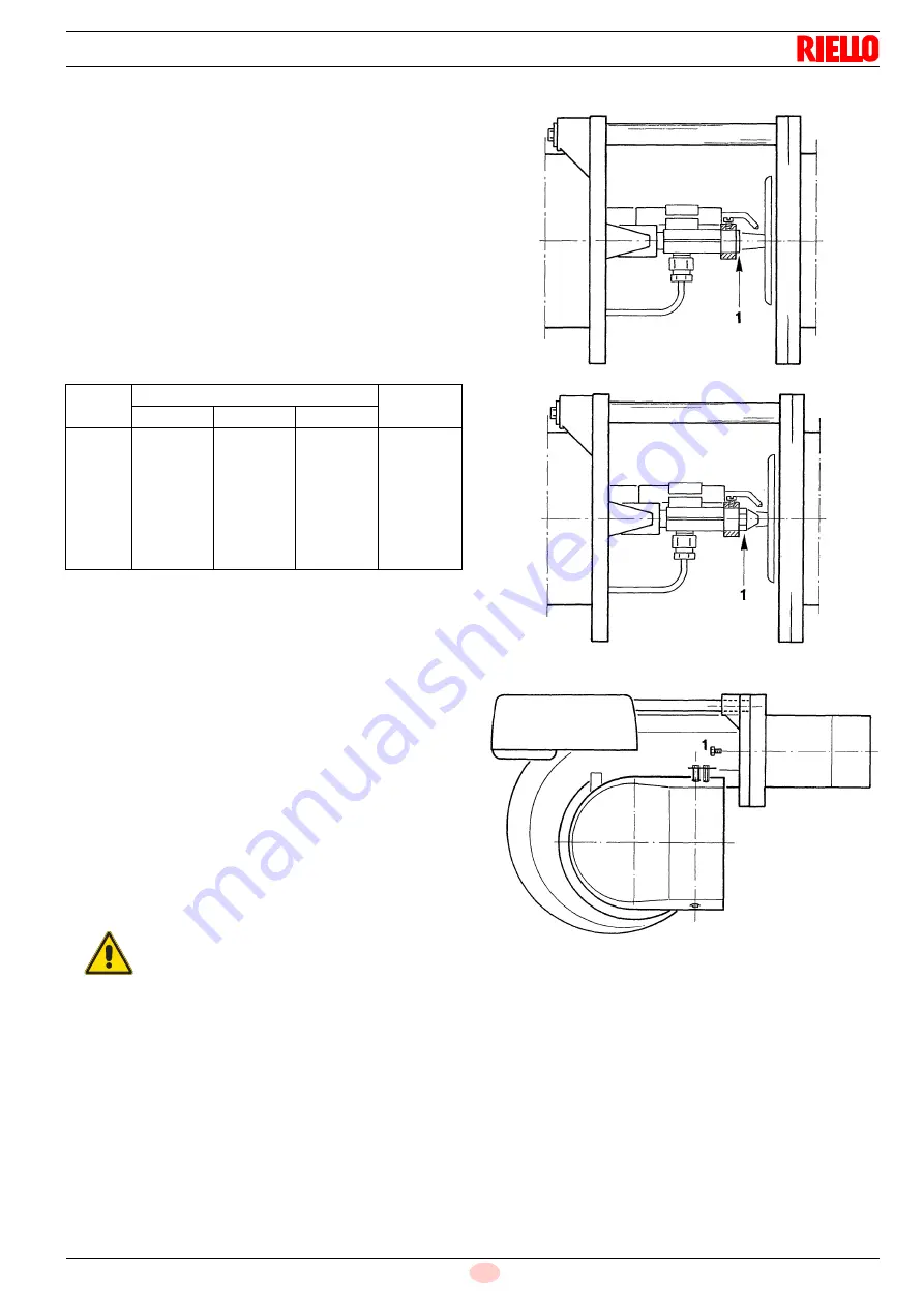
Nozzle assembly
With the burner open on the slide bars as shown in Fig. 9 on
page 14, unscrew and remove the plastic plug 1)(Fig. 10).
Screw the nozzle 1)(Fig. 11) into the same place using a 16 mm
wrench.
Lastly, close the burner by screwing in the two screws 1)(Fig. 12).
GHP
kg/h
(1)
kW
12 bar
10 bar
12 bar
14 bar
4.00
4.50
5.00
5.50
6.00
6.50
7.00
7.50
15.4
17.3
19.2
21.1
23.1
25.0
26.9
28.8
17.0
19.1
21.2
23.3
25.5
27.6
29.7
31.8
18.4
20.7
23.0
25.3
27.7
30.0
32.3
34.6
201.6
226.5
251.4
276.3
302.4
327.3
352.3
377.2
WARNING
➤
Do not use any sealing products such as gas-
kets, sealing compound, or tape.
➤
Be careful to avoid damaging the nozzle seal-
ing seat.
➤
The nozzle must be screwed into place tightly
but not to the maximum torque value pro-
vided by the wrench.
Fig. 10
D406
Fig. 11
D407
Fig. 12
D409


