22
CHAPTER
6
Burner start up and adjustment
6.2
Pressure switches setting
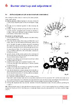
Air pressure switch
Adjust the air pressure switch after having performed all other burner adjustments with
the air pressure switch set to the start of the scale (Fig. 28).
With the burner operating at max. output, increase adjustment pressure by slowly turning
the relative knob clockwise until the burner locks out. Then turn the knob anti-clockwise
by about 20% of the set point and repeat burner starting to ensure it is correct.
If the burner locks out again, turn the knob anticlockvise a little bit more.
Attention:
as a rule, the air pressure switch must limit the CO in the fumes to less than
1% (10.000 ppm). To check this, insert a combustion analyser into the chimney, slowly
close the fan suction inlet (for example with cardboard) and check that the burner locks
out, before the CO in the fumes exceeds 1%.
Maximum gas pressure switch
Adjust the maximum gas pressure switch after having performed all the other burner
adjustments with the pressure switch set at the end of the scale (Fig. 29).
With the burner operating at maximum output, decrease adjustment pressure by slowly
turning the relative knob anti-clockwise until the burner locks out.
Then turn the knob clockwise by 0,2 kPa and repeat burner starting to ensure it is uniform.
If the burner locks out again, turn the knob anti-clockwise again by 0,1 kPa.
Minimum gas pressure switch
Adjust the minimum gas pressure switch after having performed all the other burner
adjustments with the pressure switch set at the start of the scale (Fig. 30).
With the burner operating at maximum output, increase adjustment pressure by slowly
turning the relative knob clockwise until the burner locks out.
Then turn the knob anti-clockwise by 0,2 kPa and repeat burner starting to ensure it is
uniform.
If the burner locks out again, turn the knob anti-clockwise again by 0,1 kPa.
6.3
Final checks
Before leaving the plant:
•
ensure the adjustment and safety devices work correctly;
•
check all the mechanical blocking systems on the adjustment devices are tightly closed.
.
1 kPa = 10 mbar
D2215
Fig. 28
D3571
Fig. 29
D3571
Fig. 30
Summary of Contents for DB 4 LSM C13
Page 2: ......
Page 61: ...1...
Page 69: ...9 3 3 1 1 2 3 M12 X 25 1 2 1 2 3 3 D12015 10 7 3 4 1 1 6 5 6 2 4 3 3 20110636...
Page 71: ...11 3 3 3 12 A A 8 10mm 4 4 5mm 12 D8665...
Page 72: ...12 4 4 1 1 2 3 3 3 4 1 6 13 1 3 4 5 D8416 2 6...
Page 73: ...13 4 4 2 D7543 C GF HPG LPG MM PA PGM PGm RG SRV VE VPS VR VS 0 5 4 bar 500 mbar 14...
Page 75: ...15 5 5 2 SQM 10 1 4 2 3 5 6 7 1 2 0 20 3 20 4 5 20 130 1 4 17 D1500...
Page 78: ...18 5 5 5 19 20 21 D2213 D2215 19 20 21 D2214...
Page 79: ...19 5 5 6 EN 267 20 A B D3509 22 2...
Page 83: ...23 7 7 1 UV 70 A 187 V 100 A c c 100 F 1V c c 7 2 1 2 3 4 5 1 2 3 4 5 6 D1143 31...
Page 86: ...26 7 VR VR VS VR...
Page 87: ...27 8 SQM 10 MB PA PGM PO SM TA TB UV UV VF VR VRS VS 3 5 6 7 6 3 2 8 5...
Page 89: ......
Page 90: ......
Page 91: ......

