7
CHAPTER
2
Burner description
2.5
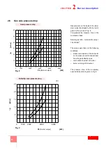
Air side pressure drop
(taken upstream from the completely open air damper)
The pressure curves refer to the different adjustment conditions for the combustion head. Refer to Paragraph
5.1
InIn the case of air supply at a higher temperature than 20°C and/or an altitude higher than 100 m. a.s.l., the pressure drop in the
head that is shown in the graph must be multiplied by the
K
c
coefficient as indicated in the table below.
Example
Burnt output = 4000 kW - Altitude = 750 m. a.s.l. - Combustive air temperature = 120 °C
From the diagram (curve 3), with an output of 4000 kW, a total pressure drop (head + air damper) is shown of:
p
20
= 7 mbar
(combustive air at 20 °C and altitude 100 m. a.s.l.).
The table gives a multiplying coefficient, for combustive air at 120 °C and altitude 750 m. a.s.l., equal to
K
c
= 1.449.
The total pressure drop of the burner head is:
p
=
p
20
x
K
c
= 7 x 1.449 = 10.14 mbar.
Altitude
K
c
Air temperature °C
m. a.s.l.
0
20
40
60
80
100
120
140
160
180
200
220
250
0
0.920
0.988
1.055
1.122
1.190
1.257
1.325
1.392
1.459
1.527
1.594
1.662
1.763
100
0.932
1.000
1.069
1.137
1.205
1.273
1.342
1.410
1.478
1.547
1.615
1.683
1.786
500
0.976
1.047
1.119
1.190
1.262
1.333
1.405
1.477
1.548
1.620
1.691
1.763
1.870
750
1.007
1.080
1.154
1.228
1.302
1.375
1.449
1.523
1.596
1.670
1.744
1.818
1.928
1000
1.038
1.114
1.190
1.266
1.342
1.418
1.494
1.570
1.646
1.722
1.798
1.874
1.988
1250
1.069
1.147
1.226
1.304
1.382
1.460
1.539
1.617
1.695
1.774
1.852
1.930
2.048
1500
1.102
1.182
1.263
1.344
1.425
1.505
1.586
1.667
1.747
1.828
1.909
1.990
2.111
1750
1.130
1.213
1.295
1.378
1.461
1.544
1.626
1.709
1.792
1.875
1.957
2.040
2.164
2000
1.174
1.260
1.346
1.432
1.518
1.604
1.690
1.776
1.862
1.948
2.034
2.120
2.249
2250
1.206
1.294
1.382
1.471
1.559
1.647
1.736
1.824
1.912
2.001
2.039
2.177
2.310
2500
1.251
1.343
1.434
1.526
1.618
1.709
1.801
1.893
1.984
2.076
2.168
2.259
2.397
2750
1.284
1.378
1.472
1.566
1.660
1.754
1.848
1.942
2.036
2.130
2.224
2.318
2.460
3000
1.320
1.417
1.514
1.610
1.707
1.804
1.901
1.997
2.094
2.191
2.287
2.384
2.529
Fig. 7
Burner output
Pb [kW]
p [
m
bar
]
60
50
40
30
20
10
DB6
DB4
0 3000 4000 5000 6000 7000 8000
250°C
250°C
DB3
D8115
Summary of Contents for DB 4 LSM C13
Page 2: ......
Page 61: ...1...
Page 69: ...9 3 3 1 1 2 3 M12 X 25 1 2 1 2 3 3 D12015 10 7 3 4 1 1 6 5 6 2 4 3 3 20110636...
Page 71: ...11 3 3 3 12 A A 8 10mm 4 4 5mm 12 D8665...
Page 72: ...12 4 4 1 1 2 3 3 3 4 1 6 13 1 3 4 5 D8416 2 6...
Page 73: ...13 4 4 2 D7543 C GF HPG LPG MM PA PGM PGm RG SRV VE VPS VR VS 0 5 4 bar 500 mbar 14...
Page 75: ...15 5 5 2 SQM 10 1 4 2 3 5 6 7 1 2 0 20 3 20 4 5 20 130 1 4 17 D1500...
Page 78: ...18 5 5 5 19 20 21 D2213 D2215 19 20 21 D2214...
Page 79: ...19 5 5 6 EN 267 20 A B D3509 22 2...
Page 83: ...23 7 7 1 UV 70 A 187 V 100 A c c 100 F 1V c c 7 2 1 2 3 4 5 1 2 3 4 5 6 D1143 31...
Page 86: ...26 7 VR VR VS VR...
Page 87: ...27 8 SQM 10 MB PA PGM PO SM TA TB UV UV VF VR VRS VS 3 5 6 7 6 3 2 8 5...
Page 89: ......
Page 90: ......
Page 91: ......


