Riello 887T Modulating Operation Download Page 59

57

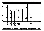
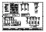
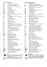
KEY TO ELECTRICAL LAYOUT
A1

-

Control box

B1

-

Internal output power regulator RWF

B2

-

External output power regulator RWF

BA

-

DC input 0...20 mA, 4...20 mA

BA1

-

DC input 0...20 mA, 4...20 mA for modifying the 
remote setpoint

BP

-

Pressure probe

BP1

-

Pressure probe

BR

-

Remote setpoint voltage divider

BT1

-

Thermocouple probe

BT2

-

Probe Pt100 with 2 wires

BT3

-

Probe Pt100 with 3 wires

BT4

-

Probe Pt100 with 3 wires

BTEXT

-

External probe for the climatic compensation of the 
setpoint

BV

-

DC voltage input 0...1 V, 0...10 V

BV1

-

DC voltage input 0...1 V, 0...10 V for modifying the 
remote setpoint

CN1

-

Ionisation probe connector

F1

-

Fan motor thermal cut-out

F3

-

Auxiliary fuse

H1

-

Signal light for burner on

H2

-

Signal light for motor trip

H3

-

Signal light for burner lock-out

ION

-

Ionisation probe

KL1

-

Direct start and star/delta starter line contactor

KT1

-

Star-powered/delta-powered starter /delta contactor

KS1

-

Star-powered/delta-powered starter /star-powered 
contactor

KST1

-

Star-powered/delta -powered starter timer

K1

-

Fan on voltage free contact relay

K2

-

Motor lock-out voltage free contact relay

K3

-

Burner lock-out voltage free contact relay

K6

-

Burner on voltage free contact relay

MV

-

Fan motor

PA

-

Air pressure switch

PE

-

Burner ground

PGMin

-

Minimum gas pressure switch

PGM

-

Maximum gas pressure switch

RS

-

Remote lock-out reset button

S1

-

Emergency stop push-button

S2

-

Switch for following operations: 
off-automatic-manual

S4

-

Button for: power increase/reduction

SH3

-

Burner reset button and lockout warning

SM

-

Servomotor

TA

-

Ignition transformer

TL

-

Limit pressure switch/thermostat

TR

-

Control pressure switch/thermostat

TS

-

Safety pressure switch/thermostat

Y

-

Gas adjustment valve + gas safety valve

YVPS

-

Gas leak detection control device

X1

-

Main supply terminal strip

X2

-

RWF terminal strip

XAUX

-

Auxiliary terminal strip

XPGM

-

Maximum gas pressure switch connection plug

XPGM1

-

Maximum gas pressure switch connection plug

XRWF

-

Output power regulator RWF terminal strip

XS

-

Flame detectors connector

XSM

-

Air and gas servomotors connector

NOTE

Wiring must be performed by qualified personnel in

accordance with the regulations in force in the

country of destination.

Riello S.p.a. declines all responsibility for changes or wiring
performed in any way other than that illustrated in these dia-
grams.

LÉGENDE SCHÉMAS ELECTRIQUE
A1

-

Coffret de sécurité

B1

-

Régulateur de puissance RWF intérieur

B2

-

Régulateur de puissance RWF extérieur

BA

-

Entrée avec courant DC 0...20 mA, 4...20 mA

BA1

-

Entrée avec courant DC 0...20 mA, 4...20 mA pour 
décalage valeur de consigne à distance

BP

-

Sonde de pression

BP1

-

Sonde de pression

BR

-

Potentiomètre valeur de consigne à distance

BT1

-

Sonde avec thermocouple

BT2

-

Sonde Pt100 à 2 fils

BT3

-

Sonde Pt100 à 3 fils

BT4

-

Sonde Pt100 à 3 fils

BTEXT

-

Sonde externe pour la compensation climatique de 
la valeur de consigne

BV

-

Entrée avec tension DC 0...1 V, 0...10 V

BV1

-

Entrée avec tension DC 0...1 V, 0...10 V pour déca-
lage valeur de consigne à distance

CN1

-

Connecteur sonde d'ionisation

F1

-

Relais thermique moteur ventilateur

F3

-

Fusible auxiliaire

H1

-

Signal lumineux brûleur allumé

H2

-

Signal lumineux blocage moteur

H3

-

Signal lumineux blocage brûleur

ION

-

Sonde d'ionisation

KL1

-

Contacteur de démarrage direct et de ligne démar-
reur étoile/ triangle

KT1

-

Contacteur triangle démarreur étoile/triangle

KS1

-

Contacteur étoile démarreur étoile/triangle

KST1

-

Temporisateur démarreur étoile/triangle

K1

-

Relais sortie contacts propres ventilateur allumé

K2

-

Relais sortie contacts propres blocage moteur

K3

-

Relais sortie contacts propres blocage brûleur

K6

-

Relais sortie contacts propres brûleur allumé

MV

-

Moteur ventilateur

PA

-

Pressostat air

PE

-

Mise à la terre brûleur

PGMin

-

Pressostat gaz mini

PGM

-

Pressostat gaz maxi

RS

-

Bouton de déblocage à distance

S1

-

Bouton arrêt d’urgence

S2

-

Sélecteur: éteint / automatique / manuel

S4

-

Sélecteur: augmentation / diminution puissance

SH3

-

Bouton de déblocage du brûleur et signal de blo-
cage

SM

-

Servomoteur

TA

-

Transformateur d’allumage

TL

-

Thermostat/ Pressostat de limite

TR

-

Thermostat/ Pressostat de réglage

TS

-

Thermostat/ Pressostat de sécurité

Y

-

Vanne de réglage gaz + vanne de sécurité gaz

YVPS

-

Dispositif de contrôle d’étanchéité vannes

X1

-

Plaque à bornes alimentation principale

X2

-

Plaque à bornes pour kit RWF

XAUX

-

Plaque à bornes auxiliaire

XPGM

-

Connecteur pressostat gaz maxi

XPGM1

-

Connecteur pressostat gaz maxi

XRWF

-

Plaque à bornes régulateur de puissance RWF

XS

-

Connecteur détecteurs flamme

XSM

-

Connecteur servomoteurs air et gaz

REMARQUE
Les branchements électriques doivent être
effectués par du personnel qualifié, conformément
aux normes en vigueur dans le pays de destination.

Riello S.p.A. décline toute responsabilité en cas de modifica-
tions ou de branchements autres que ceux représentés sur ces
schémas.

Summary of Contents for 887T

Page 1: ...entretien Bruciatori di gas ad aria soffiata Gas Gebl sebrenner Forced draught gas burners Br leurs gaz air souffl Funzionamento modulante Modulierender Betrieb Modulating operation Fonctionnement mod...

Page 2: ......

Page 3: ...Bruciatori Direttore Ricerca e Sviluppo RIELLO S p A Direzione Bruciatori Ing U Ferretti Ing F Comencini Konformit tserkl rung gem ISO IEC 17050 1 Hergestellt von RIELLO S p A Anschrift Via Pilade Rie...

Page 4: ...tment Research Development Director RIELLO S p A Burner Department Mr U Ferretti Mr F Comencini D claration de conformit d apr s ISO IEC 17050 1 Constructeur RIELLO S p A Adresse Via Pilade Riello 7 3...

Page 5: ...b 37 St rungen m gliche Ursachen empfholene Abhilfen 39 Anhang Zubeh r 42 Schaltplan 44 D CONTENTS Technical data page 8 Electrical data 8 Designation of burners 9 List of available models 9 Burner de...

Page 6: ...Gas G20 G25 mbar 34 3 40 2 37 6 56 1 44 8 64 4 45 5 81 2 Funzionamento Continuo Impiego standard Caldaie ad acqua a vapore ad olio diatermico Temperatura ambiente C 0 40 Temperatura aria comburente C...

Page 7: ...mento continuo 1 stop ogni 72 h Alimentazione elettrica del sistema 3 400 50 3 230 50 Tensione ausiliari 230 50 60 R S 500 M TC Emissione Classe 1 EN267 EN676 MZ Classe 2 EN267 EN676 BLU Classe 3 EN26...

Page 8: ...ng 2 Gas G20 G25 mbar 34 3 40 2 37 6 56 1 44 8 64 4 45 5 81 2 Betrieb Dauerbetrieb Standardeinsatz Heizkessel mit Wasser Dampf diathermischem l Raumtemperatur C 0 40 Temperatur Verbrennungsluft C max...

Page 9: ...chaltung in 24 Std Dauerbetrieb 1 Abschaltung in 72 Std Stromversorgung des Systems 3 400 50 3 230 50 Spannung der Hilfskreise 230 50 60 R S 500 M TC Emission Klasse 1 EN267 EN676 MZ Klasse 2 EN267 EN...

Page 10: ...ivery 2 Gas G20 G25 mbar 34 3 40 2 37 6 56 1 44 8 64 4 45 5 81 2 Operation Continuous Standard applications Boilers water steam diathermic oil Ambient temperatur C 0 40 Combustion air temperature C ma...

Page 11: ...king 1 stop every 72 h Electrical supply to the system 3 400 50 3 230 50 Auxiliary voltage 230 50 60 R S 500 M TC Emission Class 1 EN267 EN676 MZ Class 2 EN267 EN676 BLU Class 3 EN267 EN676 MX Class 2...

Page 12: ...Pression du gaz la puissance max 2 Gaz G20 G25 mbar 34 3 40 2 37 6 56 1 44 8 64 4 45 5 81 2 Fonctionnement Continuos Emploi standard Chaudi res eau vapeur huile diathermique Temperature ambiante C 0 4...

Page 13: ...Fonctionnement continuos 1 arr t min en 72 heures Alimentation lectrique du syst me 3 400 50 3 230 50 Tension auxiliaires 230 50 60 R S 500 M TC mission Classe 1 EN267 EN676 MZ Classe 2 EN267 EN676 BL...

Page 14: ...e 4 Staffa per l applicazione del kit Regolatore di potenza RWF 5 Pulsante di stop 6 Selettore spento automatico manuale 7 Selettore aumento diminuzione potenza 8 Segnalazione luminosa consenso alla p...

Page 15: ...losed the hinge can be re positioned on the opposite side DESCRIPTION OF PANEL BOARD B 1 Terminal strip for kits 2 Relay outlet clean contacts 3 Ignition transformer 4 Bracket for mounting the power r...

Page 16: ...icambi INGOMBRO B misure indicative L ingombro del bruciatore riportato in fig B Tener presente che per ispezionare la testa di combustione il bruciatore deve essere aperto ruotando la parte posterior...

Page 17: ...y RS 650 800 M BLU M16x67 8 Nuts M16 to secure the gas elbow to the manifold only RS 650 800 M BLU 1 Cable grommet kit for optional electrical connections 1 Instruction booklet 1 Spare parts list MAX...

Page 18: ...a camera di combustione sono vicine a quelle indicate dal diagramma B Se invece il bruciatore deve essere applicato ad una caldaia non omologata CE e o con dimen sioni della camera di combustione nett...

Page 19: ...burner boiler matching does not pose any problems if the boiler is CE type approved and its combustion chamber dimensions are similar to those indicated in diagram B If the burner must be combined wi...

Page 20: ...lare la protezione termica data a corredo sul boccaglio 4 B Infilare tutto il bruciatore sul foro caldaia pre cedentemente predisposto come in fig A e fissare con le viti date a corredo La tenuta bruc...

Page 21: ...B Prepare an adequate system of hoisting by hooking onto the rings 3 B Slip the thermal protection standard equip ment onto the blast tube 4 B Place entire burner on the boiler hole arranged previous...

Page 22: ...serranda tutta aperta la por tata d aria sia insufficiente possibile eseguire una taratura diversa da quella indicata dal dia gramma D spostando il tirante sul foro suc cessivo numericamente pi alto...

Page 23: ...on the basis of diagram D against the re quired maximum output Setting is pre arranged in the plant for the maximum run hole 3 When dealing with boilers featuring a strong back pressure if air deliver...

Page 24: ...one solo per versioni flangiate 10 Regolatore di pressione P2 Pressione a monte delle valvole regolatore P3 Pressione a monte del filtro L Rampa gas fornita a parte L1 A cura dell installatore Attenzi...

Page 25: ...andard the leak detection control is com pulsory for burners with maximum outputs over 1200 kW 9 Gasket for flanged versions only 10 Pressure adjuster P2 Upline pressure of valves adjuster P3 Upstream...

Page 26: ...vicino al valore desiderato Leggere sulla destra colonna 1 la pressio ne alla presa P1 A pag 22 Sommare a questo valore la presunta pres sione in camera di combustione Esempio RS 400 M BLU con gas na...

Page 27: ...Example for RS 400 M BLU with G20 natural gas Maximum output operation Gas pressure at test point P1 A pag 22 21 7 mbar Pressure in combustion chamber 2 mbar 21 7 2 19 7 mbar A pressure of 19 7 mbar c...

Page 28: ...ne di 130 in 42 s Non modificare la regolazione fatta in fabbrica alle camme di cui dotato solo controllare che esse siano come sotto riportato 1 Camma 130 Limita la rotazione verso il massimo 2 Camma...

Page 29: ...vomotor provides simultaneous adjust ment of the air damper by means of the variable profile cam and the gas butterfly valve It rotates through 130 degrees in 42 seconds Do not alter the factory setti...

Page 30: ...fino a quando il servomotore ha chiuso la serranda aria e la farfalla del gas a 20 regolazione fatta in fabbrica Regolazione del gas Misurare la portata del gas al contatore Se bisogna diminuirla ridu...

Page 31: ...s value is to be reduced decrease the angle of cam 3 B p 26 slightly by proceeding a little at a time until the angle is changed from 20 to 18 16 If it has to be increased turn the increase output sel...

Page 32: ...alla presa di pressione 22 A p 12 PRESSOSTATO GAS DI MASSIMA B Eseguire la regolazione del pressostato gas di massima dopo aver effettuato tutte le altre rego lazioni del bruciatore con il pressostat...

Page 33: ...ir pressure switch is fitted in an absolute mode that is connected only to the pressure test point 22 A p 12 MAXIMUM GAS PRESSURE SWITCH B Adjust the maximum gas pressure switch after having performed...

Page 34: ...tinua da 100 A fondo scala Attenzione alla polarit Bruciatore Controllare che non vi siano usure anomale o viti allentate Pulire esternamente il bruciatore Combustione Qualora i valori della combustio...

Page 35: ...sure the ionisation current disconnect the plug socket on the ionisation probe cable and insert a direct current micro amperometer with a base scale of 100 A Carefully check polarities Burner Check fo...

Page 36: ...ventil falls vorhanden 10 Jahre oder 250 000 Betriebszyklen lregler falls vorhanden 10 Jahre oder 250 000 Betriebszyklen lrohre anschl sse aus Metall falls vorhanden 10 Jahre Schl uche falls vorhanden...

Page 37: ...ENTS The safety components should be replaced at the end of their life cycle indicated in the table A The specified life cycles do not refer to the war ranty terms indicated in the delivery or payment...

Page 38: ...a o la pressione bassa per cui il termostato pressostato TR chiuso il bruciatore aumenta progressivamente la potenza fino al valore MAX tratto C D Se poi la temperatura o la pressione aumenta fino all...

Page 39: ...pressure is low and the thermostat pressure switch TR is conse quently closed the burner progressively increases its output to the MAX value sec tion C D If subsequently the temperature or pressure i...

Page 40: ...ruciatore si avvia e poi resta in blocco 22 Avaria al circuito rivelazione fiamma Sostituire apparecchiatura Il bruciatore permane in preventilazione 23 Non interviene il contatto 3 del Regolare camma...

Page 41: ...f hrt an es erfolgt dann aber eine St rabschaltung 22 St rung Flammen berwachtung Ger t ersetzen Die Vorbel ftungsphase h lt an 23 Kein Ansprechen von Schaltst ck 3 Nochen 3 einstellen oder Stellantri...

Page 42: ...The burner starts and then locks out 22 Fault in flame detection circuit Replace control box The burner stays in the pre purge stage 23 Contact 3 servomotor does not operate Adjust cam 3 or replace s...

Page 43: ...marre et se bloque 22 Panne du circuit r v lation flamme Remplacer le coffret de s curit Le br leur reste en pr ventilation 23 Le contact 3 du servomoteur R gler came 3 ou remplacer le servomoteur bo...

Page 44: ...di regolazione Tipo Codice Tipo Codice Tipo Codice Tipo Codice Temperatura 100 500 C PT 100 3010110 RWF 50 RWF 50 20101190 20101191 ASZ 3010402 E5202 3010390 Pressione 0 2 5 bar 0 16 bar Sonda con us...

Page 45: ...re 100 500 C PT 100 3010110 RWF 50 RWF 50 20101190 20101191 ASZ 3010402 E5202 3010390 Pressure 0 2 5 bar 0 16 bar Probe with outlet 4 20 mA 3010213 3010214 POTENTIOMETER KIT FOR THE INDICATION OF LOAD...

Page 46: ...K16 e rampa gas Betriebsschema der LGK16 und Gasarmaturen LGK16 and gas train operational layout Sch ma fonctionnel LGK16 et rampe gaz 7 Schema funzionale LGK16 Betriebsschema LGK16 LGK16 operational...

Page 47: ...45 0 0 1 2 30 2 30 0 0 1 4 4 0 4 0 5 4 6 4 0 4 0 0 4 4 4 4 4 74 7 7 4 4 0 5 4 0 0 0 RS 400 M BLU RS 500 M BLU...

Page 48: ...46 0 0 1 20 20 0 0 1 3 3 0 3 0 4 3 5 3 0 3 0 0 3 3 3 3 3 63 6 6 3 3 0 4 3 0 RS 650 M BLU RS 800 M BLU...

Page 49: ...47...

Page 50: ...48 0 1 1 1...

Page 51: ...49 0 0 0...

Page 52: ...50 0 1 1 1...

Page 53: ...03 7 3 5 0 221 7 5 221 7 7 2 3 7 3 7 34 7 3A 3 31 1 7 3 7 31 7 314 0 1 7 04 7 2 7 0 1 3 01 7 13 7 13 7 13 4 012 441 7 012 4 7 012 4 7 012 44 5 30 01 7 3 5 7 30 7 3 6 31 7 0 6 7 31 7 31 131 7 12 7 13 7...

Page 54: ...52 0 1 0 2 3 2 5 67 8 9 8 9 8 9 8 9 2 3 4 8 679 4 8 679 1 2 1 0 2 0 2 B B 1 B C B 0 B B B B B B B 3B 3 3 B B C B 8 9 A 8 9 A RS 400 M BLU RS 500 M BLU...

Page 55: ...53 0 1 0 2 3 2 4 56 7 8 7 8 7 98 7 8 2 3 9 9 1 2 1 0 2 0 2 1 A 0 3 3 3 A RS 650 M BLU RS 800 M BLU...

Page 56: ...8 A 2 0 6 1 A 8 112B0 6 0 5 2 0 C 5 8 905 D 81 5 75 8 580 2 5 E 1120 0 0 0 F50 5 2 5 2 1 8 5 G 702 5 0 5 A H H A A H A H 8 8 8 A 8 A A I 4 I 4 I J I K I I I I I 4I 4 I I 4 I I J I 4 4 4 L L L L A L L...

Page 57: ...4 46 4 6 6 8 09 6 4 8 09 446 5 4 8 09 8 09 1 3 2 6 4 6 4 8 A 7 6 68 B 7 7 C 5 7 C 7 5 6 6 5 6 7 6 8 46 8 4 8 67 4 6 6 7 6 7 6 7 C C 6 6 C 6 C 6 C 6 7 7 7 6 7 7 7 6 6 6 75 6 6 76 5 6 76 5 4 6 6 7 6 C 7...

Page 58: ...p a declina ogni responsabilit da modifiche o collega menti diversi da quelli rappresentati in questi schemi ZEICHENERKL RUNG SCHEMEN A1 Steuerger t B1 Interner Leistungsregler RWF B2 Externer Leistun...

Page 59: ...ated in these dia grams L GENDE SCH MAS ELECTRIQUE A1 Coffret de s curit B1 R gulateur de puissance RWF int rieur B2 R gulateur de puissance RWF ext rieur BA Entr e avec courant DC 0 20 mA 4 20 mA BA1...

Page 60: ...RIELLO S p A I 37045 Legnago VR Tel 39 0442 630111 http www riello it http www riello com Con riserva di modifiche nderungen vorbehalten Subject to modifications Sous r serve de modifications...

Reviews: