- 23 -
M
ANUAL BYPASS
Using the Manual Bypass feature, the CPS can be switched to bypass. In this condition the load is powered directly by the
input mains, any disruption in the mains directly affects the load.
CAUTION:
BEFORE CARRYING OUT THE FOLLOWING SEQUENCE OF OPERATIONS, ENSURE THAT THE CPS’S
INPUT AND OUTPUT FREQUENCY COINCIDE AND THAT THE CPS IS NOT OPERATING FROM THE
BATTERY
Attention: even when the CPS is switched on, the load is disconnected in the event of a mains blackout.
If the input mains deviates from the established tolerances, the CPS automatically switches to Stdby mode and disconnects
the load.
To force the CPS into manual bypass mode, press and hold down the ON and SEL keys simultaneously for at least 4 seconds.
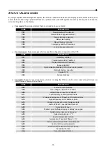
The code "C08" appears on the display.
To return to the normal operation mode press the ON and SEL keys again for at least 4 sec.
M
AINTENANCE BYPASS
(SWMB)
WARNING: Maintenance work inside the CPS is to be performed exclusively by qualified staff. Inside the
CPS there may be a voltage present even when the input, output and battery switches are open. Removal
of the CPS panels by non-qualified staff may result in injury to the operator and damage the equipment.
Below is a list of the operations to be performed in order to carry out maintenance work on the equipment without shutting off
the power supply to the load:
The CPS must power the load via the automatic bypass or the inverter, with the mains voltage present.
N.B.: If the CPS is in battery power mode, activating the maintenance bypass entails shutting off the power supply to
the load.
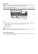
Close the maintenance bypass switch (SWMB): in this way, the input is short-circuited with the output.
Open the input switch (SWIN) and output switch (SWOUT). The display panel is turned off. Wait for the electrolytic
capacitors on the power board to discharge (about 5 minutes) and then proceed to perform the maintenance
operations.
N.B.: During this phase, with a load powered via the maintenance bypass, any disturbance on the power supply line
of the CPS will affect the devices powered (the load is connected directly to the mains, the CPS is no longer active).
Having completed the maintenance operations, proceed as follows to restart the CPS:
Close the input and output switches. The display panel is reactivated. Turn on the CPS again from the “ON” button
on the display panel. Wait for the CPS to turn on completely.
Open the maintenance bypass: the CPS resumes normal operation.
P
ROGRAMMABLE AUXILIARY SOCKETS
(E
NERGY
S
HARE
)
The EnergyShare sockets are outlets that allow for the automatic disconnection of the load applied to them in certain operating
conditions. The events that determine automatic disconnection of the EnergyShare sockets can be selected by the user through
the configuration software. For example, it is possible to select disconnection after a certain period of battery operation; or
when the pre-alarm threshold for battery discharge has been reached, or when an overloading event occurs.
By default the Energyshare sockets are not configured and therefore function as other outlets.
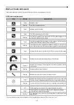
The EnergyShare function is associated with an icon on the display whose meaning is explained in the paragraph entitled
“
D
ISPLAY PANEL MESSAGES
”.
The presence and the number of these sockets will depend upon the CPS type, these sockets are easily recognised by the
EnergyShare label located beside them.
Summary of Contents for CSS SENTINEL TOWER CAM 3
Page 1: ......
Page 2: ......
Page 6: ... 4 ...
Page 8: ... 6 CPS VIEWS FRONT VIEW All models Display panel Removable front panel Ventilation grill ...
Page 39: ......
Page 40: ...0MNCAM3K0RUENUB ...


