


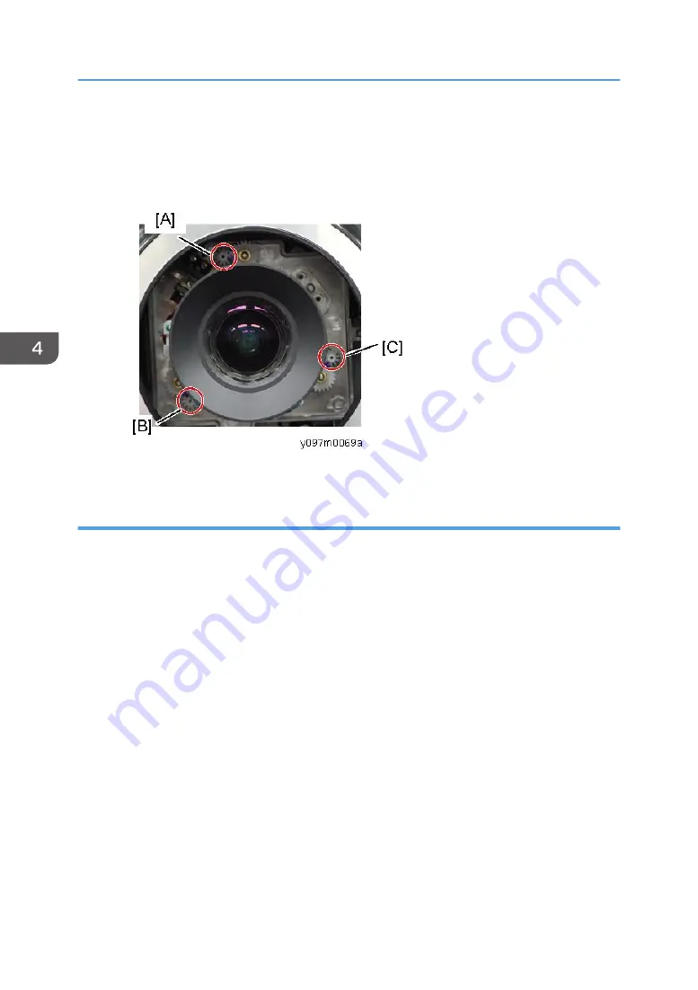
3.
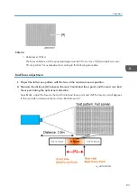
Check whether the distance is /- 3cm of the lens specifications. (Refer to
“Unbalance” of
)
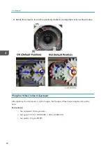
• If not, adjust the screw A, B, and C to bring the distance within specification (every screw must
be adjusted by the same amount).
• If yes, go to “Bore sight adjustment”.
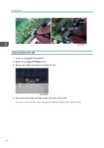
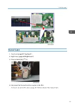
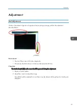
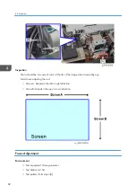
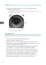
Bore sight adjustment
Perform the procedure below to make the three positions (positions 1, 2, and 3) on the screen match in
focus.
1.
Remove the lens ring. (
page 36 "Lens Ring, Projector Lens"
2.
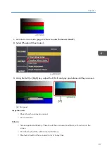
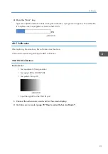
Project a “Full screen” image on the screen.
3.
Use the focus “Up” or “Down” key to adjust the focus to make position 1 in focus.
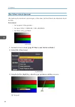
4.
When position 1 is in focus, check position 2. If position 2 is not in focus, use the “Up” or
“Down” key to adjust the focus until it is in focus.
5.
If pressing the “Up” key can focus position 2, adjust setscrew B counterclockwise. If
pressing the “Down” key can focus position 2, adjust setscrew B clockwise.
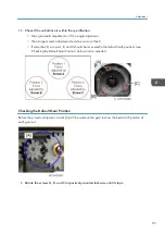
6.
Refocus position 1 and see if position 2 is also in focus. If not, repeat steps 3 to 6.
7.
Ensure position 1 is in focus. Then use the “Up” or “Down” key to focus position 3.
8.
If pressing the “Up” key can focus position 3, adjust setscrew C counterclockwise. If
pressing the “Down” key can focus position 3, adjust setscrew C clockwise.
9.
Refocus position 1 and see if position 3 is also in focus. If not, repeat steps 7 to 8.
10.
Repeat Steps 3 to 9 until positions 1, 2 and 3 are in focus at the same time.
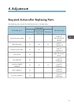
4. Adjustment
84
Summary of Contents for LU6000
Page 2: ......
Page 10: ...Projection Light 145 Light 145 8 ...
Page 28: ...Block Diagram 1 Product Information 26 ...
Page 29: ...Block Diagram 27 ...
Page 30: ...1 Product Information 28 ...
Page 44: ...4 Front Cover A x6 5 Front IR Sensor A 2 hooks 3 Replacement 42 ...
Page 46: ...4 Left Cover A x6 Right Cover 1 Top Cover page 38 Top Cover 3 Replacement 44 ...
Page 51: ...3 LAN Board A x3 x2 There are 2 connectors A at the back side Part Replacement 49 ...
Page 69: ...4 Fan Bracket A x3 5 Fan 4 A x2 Fan 5 1 Right Cover page 44 Right Cover Part Replacement 67 ...
Page 78: ...3 Replacement 76 ...
Page 100: ...When the calibration has finished a message appears 4 Adjustment 98 ...
Page 104: ...2 Select OPTION Information 3 Check the serial number 4 Adjustment 102 ...
Page 106: ...2 Select Factory Reset 3 Select Yes and then press the Enter key 4 Adjustment 104 ...
Page 116: ...5 Troubleshooting 114 ...
Page 127: ...3 Cancel selection of the proxy server as shown below and then click OK Network Test 125 ...
Page 128: ...6 Test Inspection 126 ...
Page 146: ...Cooling System Location of fans 8 Detailed Description 144 ...
Page 149: ...MEMO 147 ...
Page 150: ...MEMO 148 EN ...