
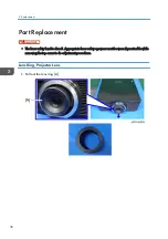
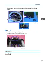
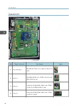

• Each of Screws [1], [2], [3] and [4] fastens adjoining covers. (For example, Screw [1] fastens the
left and rear covers.)
• If a cover is difficult to remove, removing the screws of its adjoining cover will make it easier to
remove the cover.
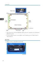
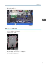
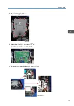
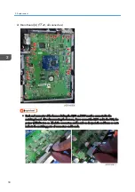
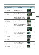
Top Cover
1.
Remove 4 screws on the back cover ( x4)
3. Replacement
38
Summary of Contents for LU6000
Page 2: ......
Page 10: ...Projection Light 145 Light 145 8 ...
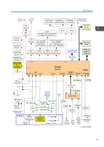
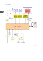
Page 28: ...Block Diagram 1 Product Information 26 ...
Page 29: ...Block Diagram 27 ...
Page 30: ...1 Product Information 28 ...
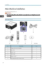
Page 44: ...4 Front Cover A x6 5 Front IR Sensor A 2 hooks 3 Replacement 42 ...
Page 46: ...4 Left Cover A x6 Right Cover 1 Top Cover page 38 Top Cover 3 Replacement 44 ...
Page 51: ...3 LAN Board A x3 x2 There are 2 connectors A at the back side Part Replacement 49 ...
Page 69: ...4 Fan Bracket A x3 5 Fan 4 A x2 Fan 5 1 Right Cover page 44 Right Cover Part Replacement 67 ...
Page 78: ...3 Replacement 76 ...
Page 100: ...When the calibration has finished a message appears 4 Adjustment 98 ...
Page 104: ...2 Select OPTION Information 3 Check the serial number 4 Adjustment 102 ...
Page 106: ...2 Select Factory Reset 3 Select Yes and then press the Enter key 4 Adjustment 104 ...
Page 116: ...5 Troubleshooting 114 ...
Page 127: ...3 Cancel selection of the proxy server as shown below and then click OK Network Test 125 ...
Page 128: ...6 Test Inspection 126 ...
Page 146: ...Cooling System Location of fans 8 Detailed Description 144 ...
Page 149: ...MEMO 147 ...
Page 150: ...MEMO 148 EN ...


