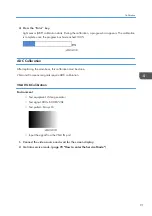

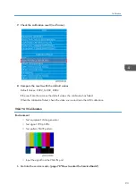

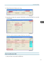

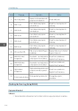
6.
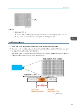
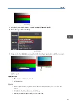
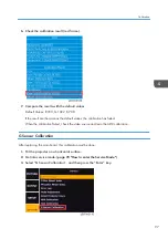
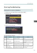
Check the calibration result (red frame).
7.
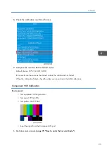
Compare the results with the default values.
Default Values: R:720, G:1022, B:708
If the result are the same as the default values, the calibration has failed.
When the calibration failed, check the video source and redo the ADC calibration.
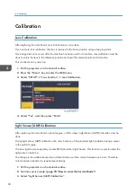
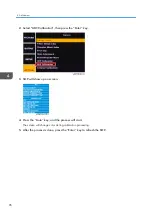
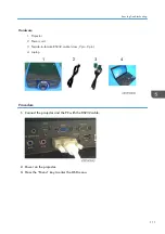
G Sensor Calibration
After replacing the main board, this calibration must be done.
1.
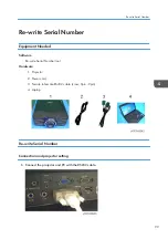
Put the projector on a horizontal surface.
2.
Get into service mode. (
page 78 "How to enter the Service Mode"
)
3.
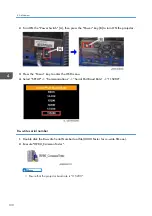
Select “G Sensor Calibration”, and then press the “Enter” key.
Calibration
97
Summary of Contents for LU6000
Page 2: ......
Page 10: ...Projection Light 145 Light 145 8 ...
Page 28: ...Block Diagram 1 Product Information 26 ...
Page 29: ...Block Diagram 27 ...
Page 30: ...1 Product Information 28 ...
Page 44: ...4 Front Cover A x6 5 Front IR Sensor A 2 hooks 3 Replacement 42 ...
Page 46: ...4 Left Cover A x6 Right Cover 1 Top Cover page 38 Top Cover 3 Replacement 44 ...
Page 51: ...3 LAN Board A x3 x2 There are 2 connectors A at the back side Part Replacement 49 ...
Page 69: ...4 Fan Bracket A x3 5 Fan 4 A x2 Fan 5 1 Right Cover page 44 Right Cover Part Replacement 67 ...
Page 78: ...3 Replacement 76 ...
Page 100: ...When the calibration has finished a message appears 4 Adjustment 98 ...
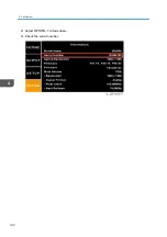
Page 104: ...2 Select OPTION Information 3 Check the serial number 4 Adjustment 102 ...
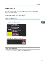
Page 106: ...2 Select Factory Reset 3 Select Yes and then press the Enter key 4 Adjustment 104 ...
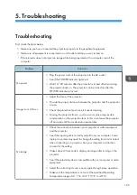
Page 116: ...5 Troubleshooting 114 ...
Page 127: ...3 Cancel selection of the proxy server as shown below and then click OK Network Test 125 ...
Page 128: ...6 Test Inspection 126 ...
Page 146: ...Cooling System Location of fans 8 Detailed Description 144 ...
Page 149: ...MEMO 147 ...
Page 150: ...MEMO 148 EN ...


