


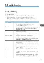


5. Troubleshooting
Troubleshooting
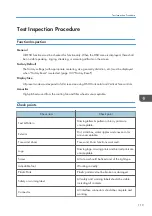
First, check the items below.
• Make sure you have connected the projector properly to the peripheral equipment.
• Make sure all equipment is connected to an AC outlet and the power is turned on.
• If the projector does not project an image while being operated with a computer, restart the
computer.
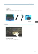
Problem
Solutions
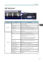
No power
• Plug the power cord of the projector into the AC outlet.
• See if the POWER indicator lights red.
• Wait 10~20 seconds after the projector is turned off when turning
the projector back on. The projector can be turned on after the
POWER indicator turns red.
Image is out of focus.
• Adjust the focus of the projector.
• Provide the proper distance between the projector and the projection
screen.
• Check the projection lens to see if it needs cleaning.
• Moving the projector from a cool to a warm place may result in
condensation on the projection lens. In this case, leave the projector
off and wait until the condensation evaporates.
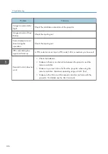
No image
• Check the connection between your computer or video equipment
and the projector.
• See if the input signal is correctly output from your computer. Some
laptop computers may need to change the setting for monitor output
when connecting to a projector. See your computer’s instruction
manual for the setting.
• It takes about 20 seconds to display an image after turning on the
projector.
• See if the selected system is compatible with your computer or video
equipment.
• Select the correct input source once again through menu operation.
• Make sure the temperature is not out of the specified Operating
Temperature range of 41 °F to 104 °F (5 °C to 40°C).
105
Summary of Contents for LU6000
Page 2: ......
Page 10: ...Projection Light 145 Light 145 8 ...
Page 28: ...Block Diagram 1 Product Information 26 ...
Page 29: ...Block Diagram 27 ...
Page 30: ...1 Product Information 28 ...
Page 44: ...4 Front Cover A x6 5 Front IR Sensor A 2 hooks 3 Replacement 42 ...
Page 46: ...4 Left Cover A x6 Right Cover 1 Top Cover page 38 Top Cover 3 Replacement 44 ...
Page 51: ...3 LAN Board A x3 x2 There are 2 connectors A at the back side Part Replacement 49 ...
Page 69: ...4 Fan Bracket A x3 5 Fan 4 A x2 Fan 5 1 Right Cover page 44 Right Cover Part Replacement 67 ...
Page 78: ...3 Replacement 76 ...
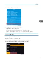
Page 100: ...When the calibration has finished a message appears 4 Adjustment 98 ...
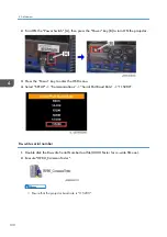
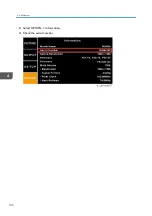
Page 104: ...2 Select OPTION Information 3 Check the serial number 4 Adjustment 102 ...
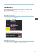
Page 106: ...2 Select Factory Reset 3 Select Yes and then press the Enter key 4 Adjustment 104 ...
Page 116: ...5 Troubleshooting 114 ...
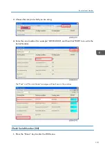
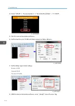
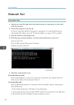
Page 127: ...3 Cancel selection of the proxy server as shown below and then click OK Network Test 125 ...
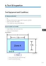
Page 128: ...6 Test Inspection 126 ...
Page 146: ...Cooling System Location of fans 8 Detailed Description 144 ...
Page 149: ...MEMO 147 ...
Page 150: ...MEMO 148 EN ...


