Type 1 Printer: Installing Options
23
2
D
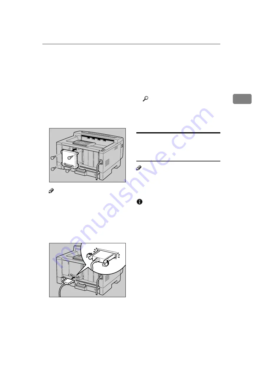
Align the screw holes of the
RS232C board over the screw
holes where the back plate used
to be. Confirm that the board is
aligned so that the jack is facing
out and is on the bottom. Press the
board firmly against the printer.
The interface connectors on the
printer and the board should
align and offer a slight resistance
before popping into place.
Note
❒
A coin can be used to attach the
screws that were removed in
step
C
.
E
Attach the cable to the connector
on the board. Fasten it with two
screws as shown in the illustra-
tion.
F
Attach the other end of the cable
to the interface connector of the
computer.
G
Plug the printer's power cord
back into the wall outlet and turn
on the printer's power switch.
H
Print a configuration page to con-
firm that the RS232C board is
properly installed.
Reference
See
“Making Printer Settings with
the Operation Panel”
in the
“Printer Reference” included as
a PDF file on the CD-ROM.
Type 1 Printer: Installing
Printer Feature Expander Type
185
Note
❒
See the inside front cover of this
manual to confirm which printer
(Type 1 Printer or Type 2 Printer)
you have.
Important
❒
The memory unit can be damaged
by small amount of static electrici-
ty. Before touching it, touch some-
thing metal to remove static
electricity from you.
❒
To make the printer recognize the
installed option, you should set up
the option with the printer driver.
❒
This printer has one slot for Printer
Feature Expander Type 185, and
you can install one of them at a
time.
A
Be sure to check the following
points:
• The printer's power switch is
turned off.
• The power cord is unplugged
from the wall outlet.
TS3P092E
TS3C030E
Summary of Contents for Laser AP1600
Page 12: ...x...
Page 46: ...Installing Options 34 2...


