background image

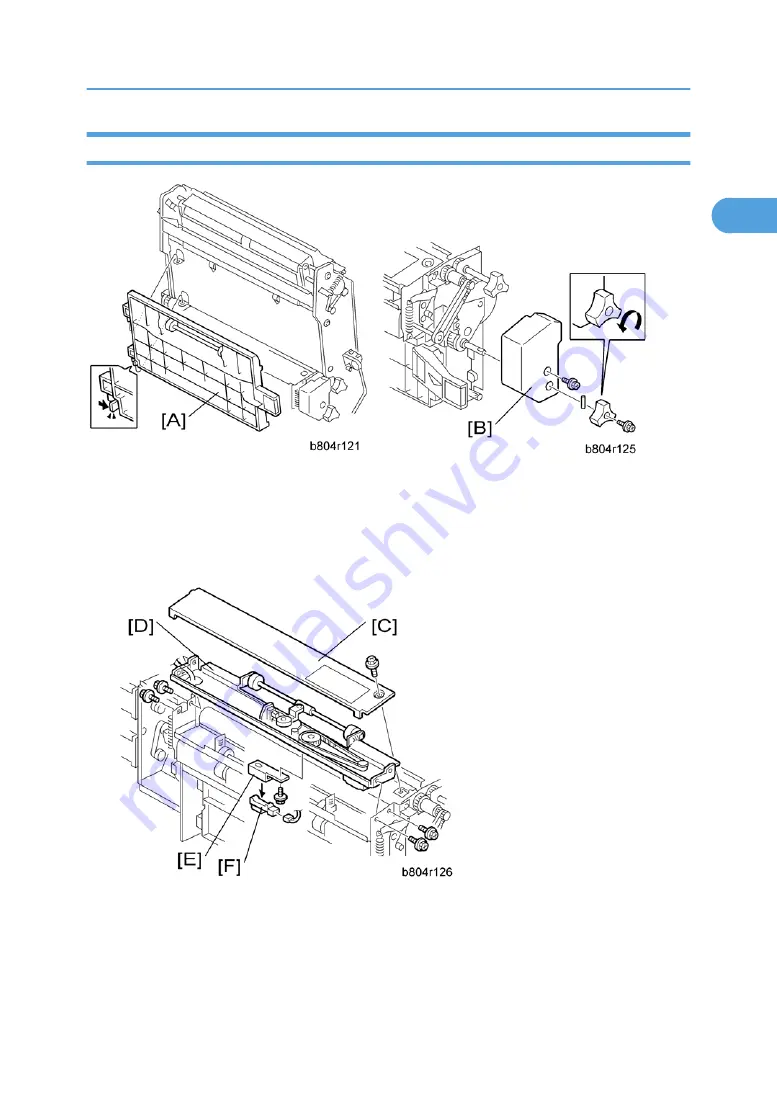
Fold Unit Exit Sensor

1. Open the front door.
2. Pull out the stapler unit (

*

 "Positioning Roller").

3. Fold unit vertical guide plate [A]
4. Fold unit inner cover [B] (

 x2, Spring pin x1)

5. Fold unit upper cover [C] (

 x1)

6. Paper clamp mechanism [D] (

 x4)

7. Fold unit exit sensor bracket [E] (

 x1)

8. Fold unit exit sensor [F] (S31) (

 x1)

Fold Unit

19

1

Summary of Contents for B804

Page 1: ...Booklet Finisher SR3020 SR3110 Finisher SR3030 SR3120 Machine Code B804 D637 B805 D636 Field Service Manual September 2011 Subject to change...

Page 2: ......

Page 3: ...fety Turn off the main power switch and unplug the machine before beginning any of the replacement procedures in this manual Symbols Used in this Manual This manual uses the following symbols See or R...

Page 4: ...r Tray Exit Sensor 10 Proof Tray Full Sensor 11 Finisher Entrance Sensor 12 Pre Stack Tray Exit Sensor 12 Stapler Unit 14 Corner Stapler 14 Positioning Roller 15 Fold Unit 16 Fold Unit 16 Fold Unit En...

Page 5: ...er Stapling 54 Stacking and Jogging 54 Stapler Movement 55 Corner Stapling 57 Booklet Stapling B804 Only 58 Booklet Pressure Mechanism 58 Booklet Stapling and Folding 59 Booklet Stapling and Folding M...

Page 6: ...4...

Page 7: ...Open the front door D 2 Small upper cover A x1 3 Upper cover B x2 4 Front door bracket C x1 5 Front door D 6 Front left side cover E x2 7 Cover F 8 Paper exit cover G x2 9 Rear cover H x2 Upper Tray...

Page 8: ...t hand 2 Pull gear B toward you to release 3 Slowly lower the tray until it stops 4 Front side cover C x1 5 Rear side cover D x1 6 Upper tray E x1 7 Tray bracket F x4 x1 shoulder screw 8 End Fence G x...

Page 9: ...Limit Switch 1 Front door front left side cover rear cover upper cover Exterior Cover 2 End fence Upper Tray End Fence 3 Upper tray exit mechanism A x4 x3 4 Upper tray limit sensor B x1 x1 5 Upper tra...

Page 10: ...Positioning Roller 1 Open the front door A 2 Pull out the stapling unit B 3 Positioning roller C x1 timing belt x1 1 Replacement and Adjustment 8 1...

Page 11: ...2 Proof tray exit sensor bracket A x1 3 Proof tray exit sensor B x1 Upper Tray Height Sensors 1 2 1 Small upper cover upper cover Exterior Cover 2 Upper tray paper height sensor bracket A x1 3 Upper t...

Page 12: ...09 x1 Exit Guide Plate Upper Tray Exit Sensor 1 Rear cover Upper covers Front door Cover Paper exit cover Exterior Cover 2 Inner cover A x2 3 Exit guide plate B x1 Link and spring x1 x1 4 Upper tray e...

Page 13: ...Proof Tray Full Sensor 1 Exit guide plate Exit Guide Plate Upper Tray Exit Sensor 2 Guide plate A hook x 2 3 Sensor bracket B x1 4 Proof tray full sensor C S11 x1 Main Unit 11 1...

Page 14: ...connect the finisher if it is connected to the copier 2 Sensor bracket A x1 3 Finisher entrance sensor B S1 x1 Pre Stack Tray Exit Sensor 1 Disconnect the finisher if it is connected to the copier 1 R...

Page 15: ...2 Sensor bracket A 3 Pre stack tray exit sensor B S2 Main Unit 13 1...

Page 16: ...Stapler Unit Corner Stapler 1 Open the front door 2 Pull out the stapler unit 3 Inner cover A x3 4 Stapler unit holder B x1 5 Corner stapler C M20 x1 1 Replacement and Adjustment 14 1...

Page 17: ...Positioning Roller 1 Open the front door A 2 Pull out the stapling unit B 3 Positioning roller C x1 timing belt x1 Stapler Unit 15 1...

Page 18: ...Fold Unit Fold Unit 1 Remove the back cover Exterior Covers 2 Open the front door The stapler unit is heavy 3 Ground cable A x1 4 Harness B x6 x6 5 Stapler unit C x4 1 Replacement and Adjustment 16 1...

Page 19: ...your hand to prevent it from falling The fold unit is heavy 6 Folding unit D x4 x2 x6 If you have replaced the folding unit 1 Read the DIP SW settings on the decal A attached to the back of the new f...

Page 20: ...ettings printed on the decal attached to the folding unit Set DIP switches 1 to 4 the switch set on the right Do not touch the other DIP switches Fold Unit Entrance Sensor 1 Pull out the stapler unit...

Page 21: ...he stapler unit Positioning Roller 3 Fold unit vertical guide plate A 4 Fold unit inner cover B x2 Spring pin x1 5 Fold unit upper cover C x1 6 Paper clamp mechanism D x4 7 Fold unit exit sensor brack...

Page 22: ...he same time do those adjustments first then replace the sensor Folding Horizontal Skew Adjustment or Fold Vertical Skew Adjustment 1 Remove the stapler unit Fold Unit 2 Guide plate A 3 Stay B x4 4 Le...

Page 23: ...of SP6 134 001 or 005 is not 0 then you must do the vertical skew adjustment Fold Vertical Skew Adjustment after you finish this horizontal skew procedure 3 Use the 10 key pad to input 2 mm for the SP...

Page 24: ...he ARDF On the copier operation panel select booklet stapling Press Start One sheet is folded 12 Remove the sheet from the lower tray 13 Hold the folded sheet with the creased side pointing down and f...

Page 25: ...for A3 paper North America Do SP6 134 005 this is for DLT paper 22 Reset it to 0 23 Do the test again 24 If the result is satisfactory this completes the adjustment or If some skew remains repeat thi...

Page 26: ...lf the measured amount of skew Example If the measure amount of skew is 1 2 mm enter 0 6 mm The range for measurement is 3 0 mm to 3 0 mm in 0 2 mm steps for every notch adjustment 8 Exit the SP mode...

Page 27: ...he front door 2 Pull out the stapler unit Positioning Roller 3 Harness cover A x2 4 Booklet stapler support stay B x4 x2 x4 5 Stapler C x4 Booklet Stapler Motor 1 Open the front door 2 Remove the stap...

Page 28: ...3 Stay A x4 4 Left plate B x4 5 Harness cover C x2 6 Booklet stapler support stay D x4 x2 x4 7 Booklet stapler E x4 8 Booklet stapler motor F x2 x1 1 Replacement and Adjustment 26 1...

Page 29: ...the booklet stapler stay This tool is included with the stapler spare part 3 Turn the gear B with your finger until it stops 4 Tighten the screws to attach to the booklet stapler motor 5 Remove the s...

Page 30: ...1 Replacement and Adjustment 28 1...

Page 31: ...ent Layout General Layout 1 Proof Tray Junction Gate 2 Punch Unit 3 Stapler Junction Gate 4 Pre Stack Junction Gate 5 Pre Stack Tray 7 Lower Tray Booklet 1 8 Folder Rollers 1 9 Folder Plate 1 10 Bookl...

Page 32: ...rting nor stapling are selected for the job Upper tray The upper tray 11 receives copies that are sorted and shifted and also receives copies that have been corner stapled Corner stapling is provided...

Page 33: ...Finisher Entrance Sensor S1 8 Upper Tray Paper Height Sensor S9 Non Sta ple Mode 9 Upper Tray Limit Sensor S12 10 Upper Tray Limit Switch SW2 11 Stacking Roller HP Sensor S13 12 Stacking Sponge Rolle...

Page 34: ...ure Plate Solenoid SOL4 7 Positioning Roller Solenoid SOL3 8 Positioning Roller Motor M14 9 Lower Tray Full Sensor Front S34 1 10 Lower Tray Full Sensor Rear S33 1 11 Main Board PCB1 12 Upper Tray Ful...

Page 35: ...M24 3 Punch HP Sensor S24 4 Punch Unit Board PCB3 5 Paper position sensor slide motor M7 6 Paper Position Slide HP Sensor S22 7 Paper Position Sensor S3 8 Punch Hopper Full Sensor S4 9 Punch Movement...

Page 36: ...r M23 1 6 Booklet Stapler EH185R Front M22 1 7 Jogger Fence Motor M15 8 Jogger Fence HP Sensor S15 9 Corner Stapler Movement Motor M6 10 Stapling Tray Paper Sensor S14 11 Corner Stapler EH530 M20 12 C...

Page 37: ...ttom Fence HP Sensor S28 8 Fold Unit Entrance Sensor S26 9 Clamp Roller Retraction Motor M8 10 Fold Unit Exit Sensor S31 Summary of Electrical Components Here is a general summary of all the electrica...

Page 38: ...out belt that moves the stapled stacks out of the stapling tray after stapling M6 Corner Stapler Movement Motor Moves the corner stapler horizontally on a steel rod to position the stapler at the stap...

Page 39: ...5 Jogger Fence Motor Drives the jogger fences in the stapling tray to jog both sides of the stack before stapling M16 Fold Unit Bottom Fence Lift Motor Raises the bottom fence and stops when the cente...

Page 40: ...etects 2 paper in the pre stack when the copier is switched on This sensor performs no timing function The entire flow of paper through the pre stacking mechanism is controlled by motor pulse counts S...

Page 41: ...Proof Tray Exit Sensor This sensor detects and times the feeding of paper to the proof tray It also detects whether paper is present at the proof tray exit when the copier is switched on S11 Proof Tra...

Page 42: ...e steel rod where the corner stapler travels this sensor detects the home position of the corner stapler The corner stapler is in its home position when the actuator on the corner stapler unit interru...

Page 43: ...Junction Gate HP Sensor Controls the opening and closing of the stack junction gate Switches on when the stack junction gate is open and at the home position S28 Fold Bottom Fence HP Sensor Controls t...

Page 44: ...ached to the actuator arm that touches the top of stapled and folded booklets as they feed out The on off combinations of the two sensors are used to detect when the tray is full and stop the job The...

Page 45: ...e of the stack to flatten it Switches SW1 Front Door Safety Switch The safety switch that cuts the dc power when the front door is opened SW2 Upper Tray Limit SW A micro switch that cuts the power to...

Page 46: ...oof Exit Motor M4 3 Upper Tray Lift Motor M21 4 Feed Out Belt Motor M5 5 Fold Roller Motor 1 M12 6 Folder Plate Motor 1 M11 7 Positioning Roller Motor M14 8 Lower Transport Motor M3 9 Entrance Motor M...

Page 47: ...y junction gates determine the direction of paper feed after paper enters the finisher Proof Mode Proof tray junction gate A opens Staple tray junction gate B remains closed The proof tray junction ga...

Page 48: ...sed With both junction gates closed the paper goes to the upper tray Staple Mode Proof tray junction gate A remains closed Staple tray junction gate B opens The staple tray junction gate directs the p...

Page 49: ...ack tray as the 2nd sheet of Set 2 5 starts to descend C As the 2nd sheet of Set 2 continues to descend the 1st sheet of Set 2 is fed from the pre stack tray At this time the leading edges 6 of both s...

Page 50: ...or A4 B5 and LT paper In one staple mode one sheet goes to the pre stacking tray Then two sheets go to the stapler tray at the same time In two staple mode and booklet mode three sheets go to the pre...

Page 51: ...ve has only one upper tray full sensor the higher sensor at H The B805 has two upper tray full sensors the upper and lower sensor at H On the B805 the upper sensor detects tray full for heavier paper...

Page 52: ...activates sensor C D is not used for staple mode Staple Mode Operation The upper tray lowers the prescribed dis tance immediately after the stack exits The upper tray rises until the actuator acti vat...

Page 53: ...om the tray If the lower tray is not installed this is detected if the front and rear sensors remain OFF the machine will not operate in the booklet staple and fold mode When booklet mode is selected...

Page 54: ...low Tell the operators that the number of sheets that the lower tray can hold will vary greatly Lower Tray Full Condition Table A3 DLT 1 Sht 2 Sht 3 Sht 4 Sht 5 Sht 6 Sht 7 Sth 8 Sht 9 Sht Full 1 3 Cn...

Page 55: ...t with 5 sheets of A4 LT paper the machine checks every 100 ms for the Full 2 condition If the Full 2 condition occurs 20 times shaded block in the table above the machine detects that the tray is ful...

Page 56: ...the sides of the selected paper size When each sheet passes the pre stack tray exit sensor S2 and enters the stapling tray The jogger fence motor switches on and moves the jogger fences to within 5 5...

Page 57: ...ogger motor at the end of the job After the last sheet feeds The stapling edge pressure plate solenoid E SOL4 switches on and pushes the pressure plate F onto the stack to press down the edge for stap...

Page 58: ...he stapler waits for the signal to fire or swivel and for diagonal stapling If the stack is to be stapled at two positions The stapler movement motor moves the stapler to the front position and staple...

Page 59: ...by the stapler motor A inside the stapler unit The stapler hammer B fires the stapler C The cartridge set sensor D detects the cartridge at the correct position The staple end sensor E detects the st...

Page 60: ...itioning roller and the jogger fences the stack feed out belt moves In booklet mode immediately after the edges are aligned by the positioning roller and jogger fences the booklet pressure solenoid sw...

Page 61: ...Pawl 2 7 Positioning Roller 8 Booklet Pressure Roller Rear 9 Jogger Fences x2 10 Pre Stack Exit Roller 13 Corner Stapler M20 14 Stapling Tray Paper Sensor S14 15 Feed Out Belt 16 Fold Unit Bottom Fen...

Page 62: ...ides of the stack 2 The pressure plate 3 and booklet pressure roller 4 press down on the sheet The stack feed out belt switches on and the pawl 5 on the feed out belt catches the bottom of the stack a...

Page 63: ...llers 7 8 and clamp rollers 9 rotate and feed the stack past the closed stack junction over the top and down toward the bottom fence 10 At the same time the fold unit bottom fence descends from its ho...

Page 64: ...es to the left and advances 1 3 its maximum horizontal stroke and exerts 20 kg 44 lb of pressure at the fold rollers 4 9 With the fold plate pushing the stack into nip of the fold rollers 5 the fold r...

Page 65: ...s and feeds the folded edge back until only 3 mm of the fold 5 remains at the nip 12 The fold rollers 6 rotate forward once again feed out The fold unit exit sensor 7 once again detects the edge of th...

Page 66: ...rollers 3 begin to rotate together and feed out the folded booklet to the lower tray 15 Once the trailing edge of the stack passes the fold unit exit sensor 4 the clamp rollers 5 close to be ready to...

Page 67: ...elt and stack junction gate cam E Stack Junction Gate Cam Opens and closes the stack junction gate F Stack Junction Gate The stack junction gate motor and stack junction gate cam close the stack junct...

Page 68: ...to within 3 mm of the bottom fence when closed and then open to drop the stack onto the bottom fence D Clamp Roller HP Sensor Controls the rotation of the clamp roller retraction motor and cam that o...

Page 69: ...the nip of the fold rollers and then moves right to retract Fold Rollers F Fold Roller Motor Drives forward to feed out the stack at the fold and then reverses to feed the fold in to sharpen the crea...

Page 70: ...tack and lifts the stack toward the feed out slot The exit guide plate F remains open as the stack emerges at a prescribed distance away from the exit roller Next the exit guide plate closes and the e...

Page 71: ...tivity of the feed out operation Feed Out Stacking Upper proof exit motor A drives feed roller B and stacking sponge roller C Stacking sponge roller motor D moves the sponge roller forward and back wi...

Page 72: ...r entrance roller to correct skew The finisher entrance roller C starts to rotate again and feeds the sheet into the finisher These SP codes adjust the skew operation in the punch unit SP6130 This SP...

Page 73: ...chine uses the detected position of the paper edge to calculate the correct position for punching The upper transport motor switches on and rotates the feed rollers D the prescribed distance to positi...

Page 74: ...h hole alignment SP6 128 Adjusts the punch positions in the direction of paper feed SP6 129 Adjusts the punch position perpendicular to the direction of feed For more see Section Service Tables 2 Deta...

Page 75: ...ce sensor S1 C detects paper when it enters the finisher and detects paper jams The paper position slide sensor motor M7 D extends and retracts the paper position slide that holds the paper position s...

Page 76: ...the punch unit to position it at the correct position for punching The punch movement HP sensor S21 B detects the position when it retracts switches off the punch position movement motor and stops the...

Page 77: ...er Wheel C Punch Encoder Sensor S24 D Punch HP Sensor S23 The punch drive motor M24 A turns the small notched encoder wheel B through the gap in the punch encoder sensor C S24 The sensor output is use...

Page 78: ...aper Then the punch drive motor turns clockwise to the 1 position to be ready for the next sheet of paper Punch Hopper Mechanism A Finisher Entrance Motor M1 B Punch Waste Belt C Punch Waste Hopper D...

Page 79: ...It also detects when the punch hopper is set properly Punch Unit B702 For B804 B805 77 2...

Page 80: ...ce sensor lag After finisher entrance sensor goes ON it does not go OFF after enough time to feed a sheet 1 5 times its length has elapsed R3 Proof Proof exit sensor late Afterfinisherentrancesensorgo...

Page 81: ...late After finisher entrance sensor goes ON pre stack tray exit sensor does not go OFF even after enough time to feed 1650 mm R8 to R12 Booklet Staple B700 On ly Fold unit entrance sensor late S26 The...

Page 82: ...MEMO 80...

Reviews: