11
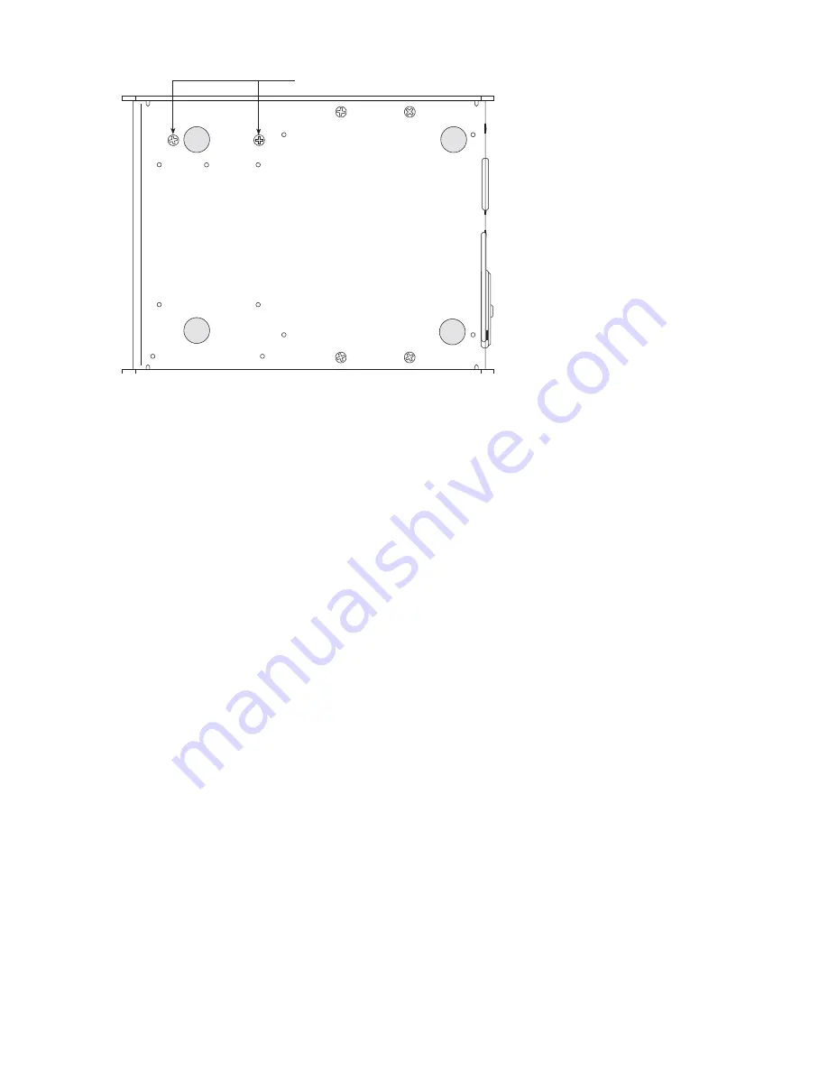
Switch module screws (2)
Figure 2-11. Bottom of SP2200, showing screws for attaching switch module
2.4.6 Time and Date Module
To install the time and date module, disconnect power to the printer and follow the procedure for removing
the covers and print mechanism as described in Section 2.4.1. Once the print mechanism is removed, continue
with the following steps:
1. If you are replacing the time and date module, carefully remove chip from socket U9 with a chip
removal tool or small screwdriver.
2. Install the time and date module in socket U9 (see Figure 2-10). The notch on the top of the chip must
face the back of the printer when installed.
3. Replace print mechanism and covers using the procedure described in Section 2.4.7.
4. Use the printer self-test procedure described in Section 2.3 to verify installation of the option.
5. To set the time and date, see Section 4.5.
2.4.7 Reassembling Print Mechanism and Covers
Once the optional hardware has been installed, use the following procedure to reassemble the print mech-
a nism and covers before testing or confi guring the option.
If any internal cables were unplugged during disassembly, ensure that they are replugged in the correct sock-
ets before continuing.
Incorrect cable connections can cause serious damage to the printer.
1. If the print mechanism has been removed, place the print mechanism in the base enclosure, then turn
the printer on its side and replace the 4 screws that hold the print mechanism to the bottom of the base
enclosure. Do not overtighten the screws.
2. Ensure that the print mechanism ribbon cable is plugged securely into connector J2 on the circuit
board (see Figure 2-10).
3. Replace electronics cover and secure with screw in back of base enclosure. The printhead must be in
the home position before replacing the cover.
4. Replace print mechanism cover and fasten with 3 screws.


