


Configuration
17
3.0
Configuration
To configure the
IQ plus 210
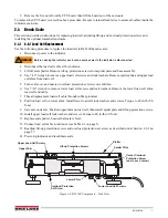
indicator, the indicator must be placed in setup mode. The setup switch is accessed by
removing the large fillister head screw on the enclosure backplate. Insert a screwdriver into the access hole and
press the switch to enter setup mode.
When the indicator is placed in setup mode, the word
CONFIG
is shown on the display. The
CONFIG
menu is the
first of the main menus used to configure the indicator. Detailed descriptions of these menus are given in
Section 3.2. When configuration is complete, press the setup switch again to exit setup mode, then replace the
setup switch access screw.
3.1
Configuration Methods
The
IQ plus 210
indicator can be configured by using the front panel buttons to navigate through a series of
configuration menus or by sending commands or configuration data to the EDP port. Configuration using the
menus is described in Section 3.1.3 on page 18.
Configuration using the EDP port can be accomplished using either the EDP command set described in Section 5.0
on page 30 or Version 2.3 or later of the Revolution
™
configuration utility.
3.1.1
Revolution Configuration
The Revolution configuration utility provides the preferred method for configuring the
IQ plus 210
indicator.
Revolution runs on a personal computer to set configuration parameters for the indicator. When Revolution
configuration is complete, configuration data is downloaded to the indicator.
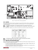
Figure 3-1. Sample Revolution Display
Revolution supports both uploading and downloading of indicator configuration data. This capability allows
configuration data to be retrieved from one indicator, edited, then downloaded to another.
To use Revolution, do the following:
1. Install Revolution on an IBM-compatible personal computer running Windows
®
3.11 or Windows 95.
Minimum system requirements are 8MB of extended memory and at least 5MB of available hard disk
space.
2. With both indicator and PC powered off, connect the PC serial port to the RS-232 pins on the indicator
EDP port.
3. Power up the PC and the indicator. Use the setup switch to place the indicator in setup mode.
4. Start the Revolution program.
Figure 3-1 shows an example of one of the Revolution configuration displays.
Revolution provides online help for each of its configuration displays. Parameter descriptions provided in this
manual for front panel configuration can also be used when configuring the indicator using Revolution: the
interface is different, but the parameters set are the same.
Summary of Contents for IQ plus 2100
Page 2: ...IQ plus 2100 Digital Bench Scale Version 1 Installation Manual PN 53415 Rev A...
Page 3: ......
Page 42: ......


