


10
IQ plus 2100 Installation Manual
2.5
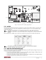
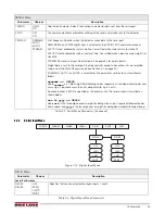
IQ Plus 210 Indicator Repair Parts
Figure 2-7. IQ Plus 210 Indicator Parts Illustration
34
22
To J6
To J4
23
7
6
5
8
12
14
2
33
37
3
36
Brown Wire
Blue Wire
From Line
Filter
19
1
20
Detail B
Ground Post Assembly
16
Back Panel
35
4
To CPU J1
15
27
24
10
11
9
26
From Inside Bottom Panel
See Detail A
Detail A
Inside Bottom Plate
31
30
28
13
29
Ground Wire
From Back Plate
To Display Board
Input Power J8
See Detail B
From Back Plate
Ground Post
From Line Filter
From Power
Cord
From Setup
Switch
Summary of Contents for IQ plus 2100
Page 2: ...IQ plus 2100 Digital Bench Scale Version 1 Installation Manual PN 53415 Rev A...
Page 3: ......
Page 42: ......


