background image

58

DC-100 Operation Manual

press the 

CLEAR

 key once as the last step.  If you want the job sequence to start over again once the task 

is done, prompt the operator to press the 

CLEAR

 key twice as the last step.

7. Repeat Steps 3-6 above until you have programmed all the steps you want.  To exit programming mode 

and return to the stand-by screen, press the 

MODE

 key twice.  At the stand-by screen you will see the 

prompt for the first step in the job sequence flashing on the second line of the display.

8.2

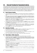
Example of Job Sequence Programming

In this example you are going to program a 6 step job sequence that will include taring out a container, 

establishing a unit weight, weighing and counting a bin of parts, and printing a label.  At the end we will return 

the scale to the beginning of the job sequence so the task can begin again.  All the operator needs to know is to 

follow the instructions on the display.

Note:

 This job sequence requires that the unit weight of the parts being counted and weighed is high enough that the initial 

sample of 10 pieces is enough to set the unit weight without the INSUFF lamp lighting up. For more information on the calculation 
of unit weights, 

1. Press 

MODE

 key until the display shows 

ITEM CODE PROGRAMMING

. The 

S

 annunciator, indicating the 

programming mode, will illuminate.

2. Press the 

+


(plus) key twice to reach the program job sequence mode.

3. Enter a 

1,

 followed by the

 * REPRINT

 key to program the first step in the job sequence.  Enter 

PLACE BIN & 

PRESS TARE

 using the alphanumeric keyboard and using 

SHIFT UP + Q

 to enter the spaces between the 

words.  Then press the 

* REPRINT 

key to move to the next step.

4. Press the 

>>

 key until you see the option for 

3 TARE (T)

.  Press the 

CODE

 key to assign the 

TARE

 key to step 

one of the job sequence.  Now when the operator follows the instruction to press the 

TARE

 key, it will 

both tare out the empty bin and move the prompt to the next job sequence step.

5. Enter a 

3

, followed by the 

* REPRINT 

key.  Enter 

PUT 10 PCS & PRESS PCS

, then press the 

* REPRINT

 key.

6. Press the 

>>

 key until you see the option for 

6 PCS

.  Press the 

CODE

 key to assign the 

PIECES

 key to step 

three of the job sequence.

7. Enter a 

4

, followed by the 

* REPRINT

 key.  Enter 

PUT PARTS/PUSH REPRINT

, then press the 

* REPRINT

 key.

8. Press the 

>>

 key until you see the option for 

2 PRINT (*)

.  Press the 

CODE

 key.

9. Enter a 

5

, followed by the 

* REPRINT

 key.  Enter 

PRESS CLEAR TWICE

, then press the 

* REPRINT

 key.

10. Press the 

>>

 key until you see the option for 

8 CLEAR

.  Press the 

CODE

 key.

11. Press the 

MODE

 key three times to return to the stand-by screen. Shortly you will see the first job 

sequence instruction flashing on the second line of the display.

8.3

Modifying a Job Sequence Step

This function allows you to change the instruction prompt that is displayed or the associated key for any existing 

step in the job sequence.

1. Press 

MODE

 key until the display shows 

ITEM CODE PROGRAMMING

. The 

S

 annunciator, indicating the 

programming mode, will illuminate

2. Press the 

+

 (plus)


key twice to reach the program job sequence mode.

3. Enter the job sequence number for the step you want to modify then press the 

* REPRINT

 key. The 

instruction prompt previously programmed will be displayed on the screen.

4. Starting at the first character you can enter a new prompt for the operator from the alphanumeric 

keyboard. The new characters will overwrite the old ones. If there are characters left at the end of the 

string that you want to delete or if you want to delete a word in the middle of the prompt, use the 

>>

 key 

to move the cursor to the space just past the character(s) you want to delete. Then press the 

CLEAR

 key to 

delete the character to the left of that space. Repeat as many times as necessary to edit the instruction 

prompt. Press the 

* REPRINT

 key to save the change.

Next you can change the key assigned to complete that job sequence step. You can scroll through the 

available keys by using the 

<<

 and 

>>

 keys. When the key you want to use is displayed, press the 

CODE

key to store it.

All manuals and user guides at all-guides.com

Summary of Contents for Digi DC-100

Page 1: ...ual To be the best by every measure Counting Scale Version 1 27 Disponible en Espa ol Visite ricelake com spanish para ver todos los materiales RLWS disponibles en Espa ol All manuals and user guides...

Page 2: ...All manuals and user guides at all guides com...

Page 3: ...3 Tare Addition or Subtraction 30 5 2 4 Tare Exchange 30 5 3 Toggling Between Gross and Net 30 5 4 Entering Unit Weights 31 5 4 1 Unit Weight Operation by Sampling 31 5 4 2 Unit Weight Operation by Ke...

Page 4: ...tron Printers 45 7 1 4 Epson Printers 46 7 2 Connecting a Barcode Scanner 46 7 2 1 Header Codes 47 7 2 2 Z Commands via Barcodes 48 7 2 3 Configuring the RS232C Port for a Scanner 48 7 2 4 Connecting...

Page 5: ...nd position it for the future growth of your business Multiple scales can be connected to the DC 100 as well as a bar code scanner external printer or keyboard When portability is required choose the...

Page 6: ...nsions 100 00 0 01 0 0001 13 x 17 DIGI S SL Platform 250 00 0 02 0 0002 17 x 21 DIGI S TL Platform 500 00 0 05 0 0005 17 x 21 DIGI S TL Platform 1500 0 0 2 0 001 24 x 28 DIGI S UL Platform 2500 0 0 2...

Page 7: ...be required for a scale operator to use certain functions of the scale A fifth mode of operation Service Mode is used by your DIGI Dealer or authorized service technician to perform initial programmi...

Page 8: ...1 DC 100 Mode Flowchart 7 ANNUNCIATOR 2 0 24 ANNUNICATOR 8 02 2 ANNUNICATOR 3 3 26 ANNUNICATOR 0 337 2 TEM 2EPORT NVENTORY 2EPORT 3HELF OCATION 0RINT TEM ODE 0ROGRAMMING ACTORY 0ROGRAMMING 0ROGRAM OB...

Page 9: ...on what mode you are in so be sure to check which mode is selected before using them Annunciator Annunciator Meaning 0 Gross weight is zero NET Display shows net weight when tare weight is entered or...

Page 10: ...re that the correct scale is selected Other Modes escape the programming screen without saving data Used to enter a known unit weight using the numeric keypad Program Mode select an item to be program...

Page 11: ...tween net weight and gross weight Adds an incrementing Sequence Number to the transaction Toggle between Inventory In Inventory Out and Non add to Inventory functions Key Description Table 1 5 DC 100...

Page 12: ...Check the insides of the box carefully to make sure you have all of the pieces The package should include the following DC 100 counting scale Stainless steel platter AC power cord DIGI certificate of...

Page 13: ...nsure a higher degree of scale stability turn in all four adjustable legs before leveling Turn out adjustable legs to level as needed Figure 2 2 Leveling Feet and Bubble 2 4 Powering Up the DC 100 Aft...

Page 14: ...e scale is turned upside down 1 Turn the DC 100 on its left side 2 Unscrew the three screws holding on the side cover to the battery compartment Figure 2 4 DC 100 Screw Location 3 Remove the side cove...

Page 15: ...n tabs to insure correct polarity Figure 2 7 Faston Tabs 6 Place the battery inside the battery compartment Then replace the battery holder bracket and secure it with the battery slot screw Figure 2 8...

Page 16: ...C or D From this stand by screen all of the basic weighing counting and inventory operations can be performed Also if any job sequence instructions have been programmed into the scale the first opera...

Page 17: ...indicating the Programming Mode will illuminate 2 Press the plus or minus keys to scroll through the programming options until you see the PROGRAM DATE screen Enter the current date using the numeric...

Page 18: ...the numeric keypad The first SPEC code SPEC 0 is displayed with SP0 AUTO POWER SAVING appearing in the first line of the weight display and its current setting ex 00 0 Disable appearing in the second...

Page 19: ...eed otherwise the INSUFF lamp lights 0 0 1 DEFAULT 1 0 2 2 0 0 04 Set New Item Code During Registration Operation Mode This allows you to add item codes while weighing in the operation mode without ha...

Page 20: ...ULT 1 Enable 14 Auto Exit From Add Mode 0 No 1 Yes DEFAULT 15 SIO Select Job Defines what the primary or standard input output port on the scale is connecting to 0 No operation DEFAULT 1 Not Used 2 PC...

Page 21: ...code Scanner 38 Barcode Scanner BCS With Header 0 Yes DEFAULT 1 No 39 Track Nprint TNP Time Out 0 2 seconds DEFAULT 1 8 seconds 2 32 seconds 40 49 SPEC 40 49 are not used by the DC 100 50 Selection of...

Page 22: ...t written to the item database 0 Disable DEFAULT 1 Enable 70 Upload Lot and Part Number If disabled lot numbers and part numbers entered during weighing operations are not uploaded to the item databas...

Page 23: ...scale using the power switch on the back of the bottom of the scale not the ON OFF key on the keyboard 6 Power scale on to re initialize the new specification settings 73 Print Barcode This option all...

Page 24: ...l Type for Scale A 0 Standard Normal load cell DEFAULT 1 Abnormal load cell with large offset 607 A D Board Type for Scale A 0 Normal DEFAULT 1 Prevent from small vibration fast change in display 2 Pr...

Page 25: ...ll DEFAULT 1 Abnormal load cell with large offset 613 A D Board Type for Scale B 0 Normal DEFAULT 1 Prevent from small vibration fast change in display 2 Prevent from medium vibration 3 Prevent from l...

Page 26: ...vent from medium vibration 3 Prevent from large vibration slow change in display 620 Tare Range Settings 0 100 full scale DEFAULT 1 50 full scale 2 5 full scale 621 Digital Tare Setting 0 Disable 1 En...

Page 27: ...Span Switch 0 No DEFAULT 1 Span switch protect 637 NOT USED 638 Display at Minus Weight 0 Minus display DEFAULT 1 Masked display 639 Masked Display at Minus Weight 0 Gross weight DEFAULT 1 Net weight...

Page 28: ...ic Unit Weight Clear Conditions 0 Disable DEFAULT 1 Over net 5D gross 21D weight stable 2 net 1D weight stable 3 net 1D quantity 0 weight stable Spec Description Table 3 2 DC 100 142 Settings All manu...

Page 29: ...f your certification specifies more stringent requirements to stay in compliance Your DIGI scale dealer has the calibrated test weights expertise and experience to perform this task for you as well as...

Page 30: ...o calibrate is displayed 7 Make sure that nothing is on the scale platform and press the CODE key to have the scale automatically search for the zero point 8 The scale displays the zero point in the q...

Page 31: ...d The weight appears in quantity window Press the REPRINT key to save the calibration data The display confirms that the span settings for calibration of the scale are being saved Finally the screen r...

Page 32: ...sidered but should not sacrifice the capacity required for the heaviest container of parts For this kind of application a dual platform scale may be the best selection There is a direct relationship b...

Page 33: ...igital tare SPEC 620 TARE RANGE must be set to the appropriate tare range value Default is 0 100 PERCENT OF FULL SCALE 5 2 1 One Touch Tare Tare Unknown 1 If the tare weight value is not known place t...

Page 34: ...one touch using the TARE key can be changed during the operation mode The new tare entered will overwrite the previous tare 1 Remove any bin or container from the scale 2 If the tare weight value is k...

Page 35: ...y 0065 as the Unit Weight If this Unit Weight were recorded and keyboard entered in future counting operations the resulting error would be 00065 55 0006536 On the other hand with entry of the Unit We...

Page 36: ...unit weight and quantity of the sample 5 4 2 Unit Weight Operation by Key Entry Unit weight operation by key entry is accomplished by using the numeric keypad to enter the known value of the unit wei...

Page 37: ...total number of parts stored in all the containers will be stored in the accumulation register 9 To print a label in the default label format showing the total press the REPRINT key This will also cle...

Page 38: ...acting Parts From Inventory The DC 100 is a self contained inventory control system capable of tracking and reporting on the stock threshold and movement of up to 2 000 items In order to track the inv...

Page 39: ...nal printer connected showing the count for this particular container in the default label format or the label format preprogrammed to be associated with this particular item 5 7 3 Sample Count and Pr...

Page 40: ...icular item See Section 6 1 2 on page 37 Table 6 1 Teraoka Codes When entering data on the 420 Plus you can use the following functions of the keyboard SPACE A B C D E F G H I 00 01 02 03 04 05 06 07...

Page 41: ...y You can continue cycling through the entry screens if you want to modify the stored data or press the MODE key to exit To store the item code and go on to program the unit weight press the REPRINT k...

Page 42: ...amples of how the setpoints can be programmed These examples can be adjusted to fit your application 13 Use the and keys to choose what type of setpoint value you want to enter Enter the first setpoin...

Page 43: ...k add new item codes override an existing tare associated with an item code inventory operations related to the item code quantity and delete an item code All storage operations are done while the sca...

Page 44: ...stored via quick add enter the item code and press the CODE key 6 2 4 Tare Override This function allows you to change the tare value already associated with an item code while in operation mode or a...

Page 45: ...all the bins or boxes of this item 6 Press the REPRINT key to store the quantities in inventory memory for this item code The display will briefly say PLEASE WAIT then return to normal 7 Remove the p...

Page 46: ...eypad 2 Press the TARE key to subtract the tare weight The net annunciator will light up and the tare weight will be displayed in the weight display Note This tare weight will be overridden by the wei...

Page 47: ...e the product on the platter and press the REPRINT key To set a new lot number press the LOT NO key and enter a lot number of up to 32 digits from the numeric keypad Then put the product on the platte...

Page 48: ...tions refer to Section 3 1 SPEC 15 SIO Select job to 3 PRINTER SPEC 16 Baud Rates SIO to the proper baud rate for your application SPEC 17 Data Length SIO to the proper length for your application SPE...

Page 49: ...o their default values of 9600 baud 8 bit data length parity none and 1 stop bit Set SPEC 31 PC PRN Output Data Method to the conditions on which you want data to be sent to the printer Set SPEC 32 Se...

Page 50: ...on which you want data to be sent to the printer Set SPEC 32 Select External Printer Type to 3 Epson Set SPEC 33 Download Label Format to 1 Disable Set SPEC 34 Print When Press key to 0 Disable or 1...

Page 51: ...thout headers set SPEC 37 BAR CODE SCANNER BCS WITH HEADER to either 0 Enable or 1 Disable Note For instructions on how to set the DC 100 s customer specifications refer to Section 3 1 Header Code ASC...

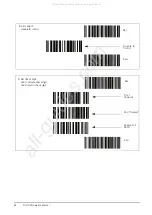
Page 52: ...able or 1 Disable depending on whether the barcodes you are scanning have headers or not see Header Codes above 7 2 4 Connecting the Scanner to the RS232C Port 7 2 5 Configuring the Keyboard Port for...

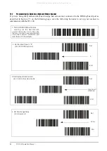
Page 53: ...bar codes to set the scanner for proper communication with the DC 100 1 Set to RS232 default values and enable RS232 interface Warning use this barcode with caution because it will clear any features...

Page 54: ...ements Disable hardware handshaking Disable CTS RTS flow control Disable XON XOFF software handshaking Set Disable Hardware Disable CTS RTS Disable Xon Xoff End 4 Set Baud Rate 4800 baud Set 4800 Baud...

Page 55: ...and Platforms 51 5 Set Interchange Delay 0 milliseconds Set 0 Milliseconds End 6 Disable ACK NAK Set Disable ACK NAK End 7 Set Suffix Set Suffix Suffix 0 Suffix D Set Set Suffix Suffix 0 Suffix D End...

Page 56: ...disable ID control Set Disable ID Control End 9 Set Check Digit don t compute check digit don t transmit check digit Set Don t Compute Don t Transmit Enable Full ASCII End All manuals and user guides...

Page 57: ...External Printers Barcode Scanners Keyboards and Platforms 53 10 Set Label Length set minimum length set length 0 Set Set minimum length Set 0 Set 0 End All manuals and user guides at all guides com...

Page 58: ...canner to communicate with the DC 100 1 Set to RS232 Default Values warning use this barcode with caution because it will clear any features you may have programmed since the scanner s installation an...

Page 59: ...nter information such as part name part number address etc the IBM PC AT keyboard can also be used to control other scale functions The IBM PC AT keyboard is mapped to the scale functions as follows N...

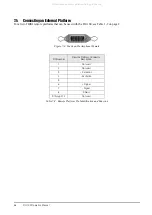
Page 60: ...DC 100 see Table 1 2 on page 2 Figure 7 4 Fourteen Pin Amphenol Female Pin Number Remote Platform Connector Description 1 Not used 2 Not used 3 Excitation 4 Excitation 5 6 Signal 7 Signal 8 Shield 9...

Page 61: ...r the first time to enter a 1 followed by the REPRINT key If you are adding steps to an existing sequence you can start at a later step Ex If you have an existing job sequence of 5 steps and want to a...

Page 62: ...quence step 5 Enter a 3 followed by the REPRINT key Enter PUT 10 PCS PRESS PCS then press the REPRINT key 6 Press the key until you see the option for 6 PCS Press the CODE key to assign the PIECES key...

Page 63: ...ng the programming mode will illuminate 2 Press the or key until you reach the program job sequence mode 3 Enter the job sequence number of the step you want to delete Instead of pressing the REPRINT...

Page 64: ...P mode or just press REPRINT key to set no password This function allows you to require a password in order to be able to access the password setting mode Press the REPRINT key to store it At this po...

Page 65: ...choose one of these options for each mode for which a password can be programmed 4 Once all of the passwords have been modified cleared or reconfirmed the scale will return to the operation mode Press...

Page 66: ...en quantity is zero Enter a quantity value Key invalid The key you have pressed is not valid during this operation Recheck the instructions for this operation to see what the valid key functions are s...

Page 67: ...out of the scale start up range Press Clear key to exit Bring the weight on the platform down to within the start up range Force balance error press clr key to exit Unable to detect a force balance d...

Page 68: ...e neglect alteration improper installation improper repair or improper testing RLWS shall be the sole judge of all alleged non conformities Such equipment has not been modified altered or changed by a...

Page 69: ...DC 100 Limited Warranty 65 All manuals and user guides at all guides com...

Reviews: