


40
420 Plus Installation Manual
6.2
Customizing Print Formats
The following sections describe procedures for
customizing the GFMT, NFMT and CFMT formats
using the EDP port, the front panel (PFORMT menu),
and the
Revolution
configuration utility.
6.2.1
Using the EDP Port
With a personal computer, terminal, or remote
keyboard attached to the
420 Plus
EDP port, you can
use the EDP command set to customize the print
format strings.
To view the current setting of a format string, type the
name of the string (GFMT, NFMT or CFMT) and
press
ENTER
. For example, to check the current
configuration of the GFMT format, type GFMT and
press
ENTER
. The indicator responds by sending the
current configuration for the gross format:
GFMT=<G> GROSS<NL>
To change the format, use the GFMT, NFMT or
CFMT EDP command followed by an equals sign (=)
and the modified print format string. For example, to
add the name and address of a company to the gross
format, you could send the following EDP command:
Indicator must be placed in the setup mode,
CONFIG
is shown on the display.
GFMT=FINE TRANSFER CO<NL>32400 WEST
HIGHWAY ROAD<NL>SMALLTOWN<NL2><G>
GROSS<NL>
A ticket printed using this format might look like the
following:
FINE TRANSFER CO
32400 WEST HIGHWAY ROAD
SMALLTOWN
1345 lb GROSS
6.2.2
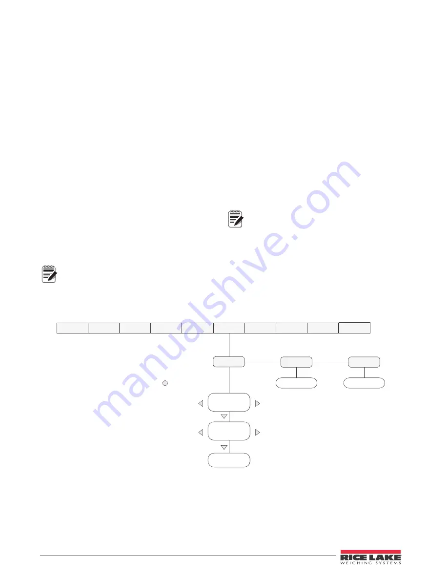
Using the Front Panel
I f y o u h a v e n o a c c e s s t o e q u i p m e n t f o r
communication through the EDP port or are working
at a site where such equipment cannot be used, you
can use the PFORMT menu (see Figure 6-1) to
customize the print formats.
Using the PFORMT menu, you can edit the print
format strings by changing the decimal values of the
ASCII characters in the format string.
Lowercase letters and some special
characters cannot be displayed on the
420
Plus
front panel (see the ASCII character
charts on page 45 and page 46) and are
shown as blanks. The
420 Plus
can send or receive any
ASCII character; the character printed depends on the
particular ASCII character set implemented for the
receiving device.
Figure 6-1. PFORMT Menu, Showing Alphanumeric Character Entry Procedure
Note
XXXXXXX
XXXXXXX
XXXXXXX
XXXXXXX
GFMT
Display first 6
characters of format
Same as GFMT
NFMT
ALGOUT
DIGIN
SETPNT
PROGRM
PFORMT
SERIAL
CALIBR
CONFIG
FORMAT
Display and edit
active character and
ASCII value
Delete active
character
Scroll right in format string
Scroll left in format string
Increment ASCII value of active character
Decrement ASCII value of active character
Press
to insert a space
before the active character
VERS
Same as GFMT
CFMT
Note


