


420 Plus Installation Manual - Print Formatting
39
6.0
Print Formatting
The
420 Plus
provides three print formats, GFMT,
NFMT, and CFMT that determine the format of the
printed output when the
key is pressed or when
a KPRINT EDP command is received. If a tare has
been entered or acquired, NFMT is used; otherwise,
GFMT is used.
Each print format can be customized to include up to
300 characters of information, such as company name
and address, on printed tickets. You can use the
i n d i c a t o r f r o n t p a n e l ( PF O R M T m e n u ) , E D P
commands, or the
Revolution
®
configuration utility to
customize the print formats.
Display will only show capital letters, press
the down arrow to view the ASCII character
decimal value on the second menu level.
Refer to Table 7-4 on page 45 and Table 7-5
on page 46 to view the ASCII character
charts.
6.1
Print Formatting Commands
Table 6-1 lists commands you can use to format the
gross, net and count print formats. Commands
included in the format strings must be enclosed
between < and > delimiters. Any characters outside of
the delimiters are printed as text on the ticket. Text
characters can include any ASCII character that can
be printed by the output device.
The default GFMT, NFMT and CFMT print formats
use only the new line (<NL>) command and the
commands for gross, net, and tare weights in
displayed units (<G>, <N>, and <T>). The default
420
Plus
print formats are shown in Table 6-2:
The <G2>, <N2>, and <T2> commands listed
in Table 6-1 print the gross, net, and tare
weights in non-displayed units—that is, in
the units not currently displayed on the
indicator.
ID numbers included in the print format string (<UID>
command) must be set using the UID EDP command.
The 300-character limit of each print format string
includes the output field length of the print formatting
commands, not the command length. For example, if the
indicator is configured to show a decimal point, the <G>
command generates an output field of 13 characters: the
10-character weight value (including decimal point), one
space, and a two-digit units identifier.
PT (preset tare) is added to the tare weight if tare was
keyed in.
Command
Description
<G>
Gross weight in displayed units
<G2>
Gross weight in non-displayed units
<N>
Net weight in displayed units
<N2>
Net weight in non-displayed units
<T>
Tare weight in displayed units
<T2>
Tare weight in non-displayed units
<A>
Accumulated weight in displayed units
<AC>
Number of accumulator events (5-digit counter)
<AD>
Date of last accumulator event
<AT>
Time of last accumulator event
<UID>
Unit ID number
<CN>
Consecutive number
<NL
nn>
New line (
nn
= number of termination (<CR/LF>
or <CR>) characters)*
<C>
Current piece count
<W>
Current piece weight
<SP
nn>
Space (
nn
= number of spaces)*
Table 6-1. Print Format Commands
Note
<SU>
Toggle weight data format (formatted/
unformatted)**
<TI>
Time
<DA>
Date
<TD>
Time & Date
Gross, net, and tare weights are 9 digits in length, including
sign (10 digits with decimal point), followed by a space and a
two-digit units identifier. Total field length with units identifier
is 12 (or 13) characters.
ID and consecutive number (CN) fields are 1–6 characters in
length, as required.
* If
nn
is not specified, 1 is assumed. Value must be in the
range 1–99.
** After receiving an SU command, the indicator sends
unformatted data until the next SU command is received.
Unformatted data omits decimal points, leading and trailing
characters.
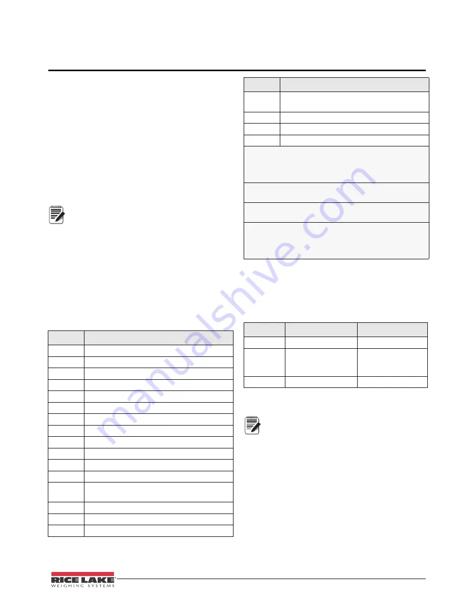
Format
Default Format String
Sample Output
GFMT
<G> GROSS<NL>
2046.81 lb GROSS
NFMT
<G> GROSS<NL>
<T> TARE<NL>
<N> NET<NL>
4053.1 lb GROSS
15.6 lb TARE
4037.5 lb NET
CFMT
<C><NL>
512 PC
Table 6-2. GFMT and NFMT Formats
Command
Description
Table 6-1. Print Format Commands
Note


