background image

25

FIGURE 20
UT Electronic Controls 1012-925A
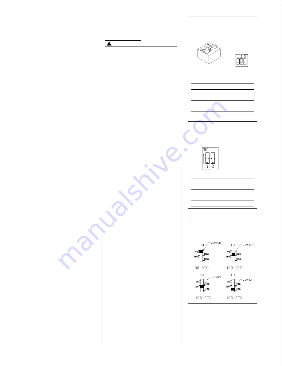
BLOWER OFF TIMINGS

OFF TIME

SWITCH 1

SWITCH 2

90 SEC.

OFF

ON

120 SEC.

OFF

OFF

160 SEC.

ON

OFF

180 SEC.

ON

ON

(TIMER IS
RED BLOCK
ON BOARD)

I335

5. After 5 seconds of inter-purge, the

igniter heats for 30 seconds. After 30
seconds, the gas valve opens for 9
seconds. If no flame is sensed, it
closes the gas valve, the igniter de-
energizes,

Both the main blower and

the inducer operate for 180 seconds
before the next ignition trial. 

6. It repeats this process up to four times.

At the end of the last try, the inducer
stops immediately.

The system is in

“soft” lock out for one hour.

7. The above sequence will repeat after a

one hour delay. It will continue
repeating until ignition is successful or
the call for heat is terminated.

8.

To reset the lock out, make and
break power either at the
thermostat or at the unit disconnect
switch for 5 to 10 seconds. 

It then

goes through another set of trials for
ignition.

SETTING BLOWER TIMINGS

The UT Electronic Controls control
boards have four quick connect
terminals for connecting the motor
speed leads. These are:

1. FAN SPEED — motor runs on this

speed when the thermostat is in the
“FAN” position.

2. COOL — connect desired cooling

speed.

3. HEAT — connect desired heating

speed.

4. HEAT/COOL — connect desired

speed when heating and cooling
speed are the same.

NOTE:

This tap not available on (-)GPJ

or (-)GLJ.

IMPORTANT

Do not connect any

motor speeds to “HEAT” or “COOL” if
you use the “HEAT/COOL” terminal.

5. If heating and continuous speed are

the same, jump across “FAN” and
“HEAT” terminals.

NOTE:

This does not apply to (-)GPJ or

(-)GLJ models because the heat tap
functions as the continuous fan tap as
well.

See Figures 19, 20 & 21 for instructions
for setting the blower “OFF” timings.

GAS FURNACE (DIRECT
DRIVE) INSTRUCTIONS FOR
CHANGING BLOWER SPEED

DISCONNECT THE ELECTRICAL
SUPPLY TO THE FURNACE BEFORE
ATTEMPTING TO CHANGE THE
BLOWER SPEED. FAILURE TO DO
SO CAN CAUSE ELECTRICAL
SHOCK RESULTING IN SEVERE
PERSONAL INJURY OR DEATH.

The blower motor is wired for blower
speeds required for normal operation
as shown.

If additional blower speed taps are
available (leads connected to “M1” and
“M2” on the electronic control), speeds
may be changed if necessary to fit
requirements of the particular
installation. Reconnect the unused
motor leads to “M1” or “M2.” Check
motor lead color for speed designation.

Heating speeds should not be reduced
where it could cause the furnace air
temperature to rise to exceed the
maximum outlet air temperature
specified for the unit.

IMPORTANT

Always check air

temperature rise after changing the
heating speed for any reason.

FIGURE 19
UT Electronic Controls 1028-928
BLOWER  OFF TIMINGS

OFF TIME

SWITCH 1

SWITCH 2

90 SEC.

OFF

ON

120 SEC.

OFF

OFF

160 SEC.

ON

OFF

180 SEC.

ON

ON

TWIN

SINGLE

NOTE: SWITCH 3 IS USED FOR
TWINNING APPLICATIONS.

ON

I402

WARNING

!

FIGURE 21
UT Electronic Controls 1012-925B
BLOWER OFF TIMINGS

Summary of Contents for GLH series

Page 1: ...INSTALLATION INSTRUCTIONS FOR UPFLOW UPFLOW HORIZONTAL AND DOWNFLOW INDUCED DRAFT GAS FURNACES GPH GPJ GLH GLJ SERIES Click anywhere in this document to return to HVAC inspection Installation Diagnosi...

Page 2: ...furnace ground to electrical panel DC microamp A flame signal hot surface ignition units Correct control voltage Measure and set heat anticipator amperage Air conditioning low voltage wires connected...

Page 3: ...THE FURNACE INSPECT ALL PARTS FOR DAMAGE PRIOR TO INSTALLATION AND START UP CONTENTS Safety Precautions 4 Installation Check List 2 General Information 5 Location Requirements and Considerations 5 Com...

Page 4: ...LATE WHEN A FURNACE IS INSTALLED SO THAT SUPPLY DUCTS CARRY AIR CIRCULATED BY THE FURNACE TO AREAS OUTSIDE THE SPACE CONTAINING THE FURNACE THE RETURN AIR SHALL ALSO BE HANDLED BY DUCT S SEALED TO THE...

Page 5: ...llation in attics as well as alcoves utility rooms closets and crawlspaces 5 IMPORTANT Support this unit when installed For attic or crawl space installation horizontal furnaces may be installed on co...

Page 6: ...D UPFLOW HORIZONTAL MODELS TOP LEFT SIDE FRONT RIGHT SIDE BOTTOM 24 1 2 26 13 16 26 5 8 24 11 32 24 11 32 19 32 9 16 24 7 16 28 1 16 26 5 8 14 3 8 11 1 2 34 1 5 8 DIA 23 15 20 D 7 8 DIA 7 8 DIA 19 32...

Page 7: ...2 23 11 32 15 5 8 23 5 8 0 0 0 1 3 6 140 lbs 15 24 1 2 23 11 32 15 5 8 23 5 8 0 0 0 1 3 6 150 lbs TOP BOTTOM 24 1 2 19 3 4 C A B D LOW VOLTAGE GAS CONNECTION ELECTRIC CONNECTION E S A R A 26 5 8 26 13...

Page 8: ...sure drop including evaporator coil if used of the entire system should not exceed 0 5 w c Be sure to have adequate space for unit filter IMPORTANT Some high efficiency filters have a greater than nor...

Page 9: ...E TO INSTALL A BASE PLATE COULD CAUSE PRODUCTS OF COMBUSTION TO BE CIRCULATED INTO THE LIVING SPACE AND CREATE POTENTIALLY HAZARDOUS CONDITIONS INCLUDING CARBON MONOXIDE POISONING OR DEATH 2 If summer...

Page 10: ...ly If this unit is mounted in a closet the door must be closed when making this check of the installation DO NOT reset the overtemperature switch without taking corrective action to assure that an ade...

Page 11: ...with tight construction contemporary construction outside air may still be required for the furnace to operate and vent properly Outside air openings should be sized the same as for a confined space...

Page 12: ...uare inch for each 2000 BTUH of total input rating for all equipment in the enclosure Here are typical duct sizes FIGURE 8 OUTSIDE AIR USING A HORIZONTAL INLET OUTLET B Method 2 One permanent opening...

Page 13: ...THE NATIONAL FUEL GAS CODE ANSI Z223 1 AND OR THE NATURAL GAS INSTALLATION CODE CSA B149 1 2 FOR PROPER INSTALLATION PRACTICES SINGLE WALL VENT CONNECTORS TO B 1 VENT OR MASONRY CHIMNEYS MAY BE USED U...

Page 14: ...l height above the highest connected equipment draft hood or flue collar 3 Must rise 1 4 per foot away from the furnace on horizontal runs and be supported with straps or hangers so it has no sags or...

Page 15: ...ust fans such as range hoods and bathroom exhausts so they will operate at maximum speed Do not operate a summer exhaust fan Close fireplace dampers 4 Follow the lighting instructions Place the applia...

Page 16: ...rnace Consult the local gas company for the location of the manual main shut off valve The gas line and manual gas valve must be adequate in size to prevent undue pressure drop and never smaller than...

Page 17: ...LP gas 54 55 WARNING LP CONVERSION NOTE For installation see specific LP kit installation instructions The valve can be converted to use liquefied petroleum LP gas by replacing the pressure regulator...

Page 18: ...LP storage tank may require supplemental heat to maintain proper pressure levels FIGURE 13 TYPICAL HOSE CONNECTION TO LINE PRESSURE TAP Maximum capacity of pipe in thousands of BTU per hour of undilu...

Page 19: ...ON THE RATING PLATE TO CHECK FURNACE INPUT 1 Make certain that all other gas appliances are shut off with the exception of pilot burners 2 Start the furnace 3 Time the meter to measure the time requir...

Page 20: ...Electrical Code Part 1 CSA Standard C22 1 and local building codes This can be obtained from National Fire Protection Association Batterymarch Park Quincy MA 02269 Canadian Standards Association 178...

Page 21: ...IONS BELOW IMPORTANT ONLY TWIN FURNACES WITH IDENTICAL CONTROL BOARDS IMPORTANT ONLY BOTTOM RETURNS CAN BE USED NO MORE THAN TWO FURNACES CAN SHARE THE SAME SUPPLY AND RETURN FURNACES MUST HAVE SAME H...

Page 22: ...22 I400 FIGURE 17 UT Electronic Controls 1028 928 CONTROL BOARD TWINNING CONNECTION SINGLE STAGE OPERATION a099201...

Page 23: ...23 FIGURE 18 UTEC 1028 928 CONTROL BOARD TWINNING CONNECTION TWO STAGE OPERATION a099301...

Page 24: ...ers go out the induced draft blower stops after a 5 second post purge and the negative pressure switch es open 9 The main blower continues until timed off by the setting on the integrated furnace cont...

Page 25: ...t available on GPJ or GLJ IMPORTANT Do not connect any motor speeds to HEAT or COOL if you use the HEAT COOL terminal 5 If heating and continuous speed are the same jump across FAN and HEAT terminals...

Page 26: ...subtract the return air temperature from the supply air temperature The difference is the temperature rise 5 Compare the measured temperature rise to the approved temperature rise range listed on the...

Page 27: ...27 BLOWER PERFORMANCE DATA GPH UPFLOW HORIZONTAL MODELS BLOWER PERFORMANCE DATA GLH DOWNFLOW MODELS...

Page 28: ...28 BLOWER PERFORMANCE DATA GLJ DOWNFLOW MODELS ONLY BLOWER PERFORMANCE DATA GPJ UPFLOW HORIZONTAL MODELS...

Page 29: ...manually reset DO NOT jumper or reset this switch If this switch should trip a qualified installer service agency or the gas supplier should be called to diagnose and or correct the source of trippin...

Page 30: ...2 125 000 and 150 000 BTUH units require removal of 7 segment of filter and frame to get proper width for a side filter TABLE 7 FILTER SIZES MAINTENANCE WARNING FIGURE 25 RESIZING FILTERS FRAME NOTE S...

Page 31: ...D SIDE RETURN FIGURE 28 DOWNFLOW FILTER INSTALLATION FILTER ROD 45 24095 01 FILTER ROD SUPPORT ANGLE AE 60520 01 FILTER SUPPORT ANGLE SEE ANGLE DETAIL AE 61883 01 FILTER ROD SUPPORT ANGLE AE 60520 01...

Page 32: ...cleaning the following procedures should be followed by a qualified installer service agency or gas supplier 1 Turn off electrical power to the furnace and set the thermostat lever to the lowest tempe...

Page 33: ...33 FIGURE 29 TROUBLESHOOTING FLOWCHART continued on next page PREPURGE...

Page 34: ...34 FIGURE 29 TROUBLESHOOTING FLOWCHART CONTINUED 92 22744 19 01...

Page 35: ...35 FIGURE 30 FOR MODELS WITH UT ELECTRONIC CONTROLS 1028 928 INTEGRATED FURNACE CONTROL AND DIRECT SPARK IGNITION...

Page 36: ...36 CM 0103 FIGURE 31 FOR MODELS WITH UT ELECTRONIC CONTROLS 1012 925 INTEGRATED FURNACE CONTROL AND HOT SURFACE IGNITION...

Reviews: