RFI 150-W-D-DD-H-1 radio modem Operation Manual
Chapter 4 Operation
MAN0065 Rev 1.7
19
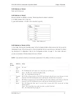
LED Indicators Mode 4
Reserved for future use.
LED Indicators Mode 5
Mode 5 indicates the RS232 port status. Table 8 specifies the Mode 5 indicators:
A red LED ind12 V (logic on);
A green LED indicates –12 volts or no connection (logic off).
LED
Number
Indicator
1 DSR
2 DCD
3 TX
4 RX
5 CTS
6 (CFG)
RTS
Table 7: Mode 4 Indicators
LED Indicators Mode 6 (CFG)
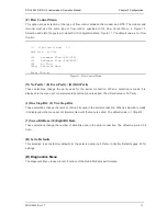
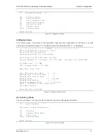
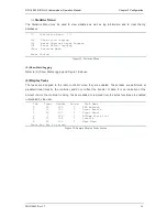
In this mode, the Aux port provides access to the Configuration Menu. Data received by the Aux port is
interpreted as part of the menu system. This mode allows the menu system to be accessed for status /
log information or configuration (refer to the Configuration section on page 7). The LEDs in Mode 6
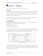
provide an indication of the link status as shown in Table 8.
NOTE
: It is possible to alter the communication parameters of the Main port in the menu system.
LED
Number
Indicator Colour
1 Network
Link
Not used.
2 Carrier
Detect
The LED illuminates and remains on in the presence of an RF carrier.
Green – The RF carrier contains valid information.
Red – See Troubleshooting on page 24.
3 Transmit
Data
RS232 Data is being moved out the RS232 port through either the main or auxiliary port (to the
terminal). The LED will alternate between red and green into indicate data movement.
4 Receive
Data
RS232 Data is being received from the RS232 port from either the main or auxiliary port (from the
terminal). The LED will alternate between red and green into indicate data movement.
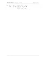
5
Online
The LED illuminates when data is received from a remote radios that contains the receiving
modems address.
Green – The received data has passed the radios error check functions.
Red – See Troubleshooting on page 24.


