


RFI 150-W-D-DD-H-1 radio modem Operation Manual
Chapter 4 Operation
MAN0065 Rev 1.7
18
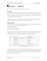
When the Modem is first turned on the display defaults to Mode 1.
LED Indicators Mode 1
Mode 1 provides link status indication. Refer to Table 5 below.
LED
Number
Indicator Colour
1 Network
Link
Not used.
2 Carrier
Detect
The LED illuminates and remains on in the presence of an RF carrier.
Green – The RF carrier contains valid information.
Red – See Troubleshooting on page 24.
3 Transmit
Data
RS232 Data is being moved out the RS232 port through either the main or auxiliary port (to the
terminal). The LED will alternate between red and green into indicate data movement.
4 Receive
Data
RS232 Data is being received from the RS232 port from either the main or auxiliary port (from the
terminal). The LED will alternate between red and green into indicate data movement.
5
Online
The LED illuminates when data is received from a remote radios that contains the receiving
modems address.
Green – The received data has passed the radios error check functions.
Red – See Troubleshooting on page 24.
6 (CFG)
Power/
Fault
This indicator will flash on / off at one-second intervals.
Green – The internal functions of the radio are OK.
Red – See Troubleshooting on page 24.
Table 5: Mode 1 Indicators
LED Indicators Mode 2
Mode 2 is reserved for future use to will provide an indication of the RSSI (Received Signal Strength
Indicator).
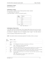
LED Indicators Mode 3
Mode 3 provides an LED bar graph indicating transmitted RF power setting (refer to (P) Tx Power Menu
page 9). When the Tx power is set to ‘off’, LED 6 (CFG) is red. If the Tx power is set to a numerical value,
a green LED bar graph is generated from LED 6 up, as shown in Table 6.
LED Number
LED Indicator [dBm]
1 37
2 34
3 30
4 27
5 20
6 (CFG)
OFF
Table 6: Mode 3 Indicators


