RFI 150-W-D-DD-H-1 radio modem Operation Manual
Chapter 4 Operation
MAN0065 Rev 1.7
17
CHAPTER 4
OPERATION
Once connected, the Crescendo-series RFI-150 is ready for operation.
Serial Ports
The Main Port passes information between the RS-232 port and the remote modem(s), along the RF link.
The local modem does not interpret the information. RF transmission begins when the first characters are
detected on the serial link (after a user configurable number of dummy characters) and stops when the
(tuneable) inter-character delay is detected.
The Auxiliary port (Aux) is not used as part of normal operation. It is supplied for Configuration Menu
access, a feature that is independent of the serial / RF transmission facilities.
Diagnostic Modes
Six diagnostic modes are offered in the Crescendo-series RFI-150. The function of the Main serial port is
the same in each mode. The modes differ in the following ways:
The function of the Aux port;
Modes 1-5 do not use the Aux port.
The meaning of the front panel LEDs.
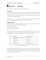
The LEDs on the Crescendo-series RFI-150 front panel provide system information, according to the
selected diagnostic mode, as described in Table 4, below. When the push-button on the front panel is
pressed the display will change to indicate the current mode of operation via a red LED.
Mode
Indication LED
Indicators
1
General data flow and radio characteristics
Individual indictors
2
RSSI Indicator
Bar graph
3
Transmit Power
Bar graph
4
Not used
Not used
5
RS-232 Port Status
Individual indicators
6 (GFG)
Auxiliary Port Configuration Menu Access
Individual indicators (as per mode 1)
Table 4: Diagnostic Modes
If the push button is held down for longer than one second a red LED will begin cycling through each
mode; pressing the button will increase the cycling rate. Once the desired mode is reached the push-
button can be released. After approximately one second delay the LEDs will provide the indications
corresponding to the selected mode.


