background image

IC Live Users Manual, ICL-F & ICL-F-DUAL

2

IMPORTANT SAFETY INSTRUCTIONS

CAUTION

To reiterate the above warnings: servicing instructions are for

use by qualified personnel only. To avoid electric shock, do

not perform any servicing other than that contained in the Ope-

ration Instructions unless you are qualified to do so. Refer all

servicing to qualified personnel.

Eindrigliche Warnung: Wartungsvorschriften dienen nur der

Benutzung durch qualifizieres Personal. Zur Vermeidung eines

elektrischen Schlages keine anderen als die in den Betriebsvor-

schriften beschriebenen Wartungsarbeiten ausführen, es sei denn

Sie sind dafür qualifiziert. Wartungsarbeiten auszuführen.

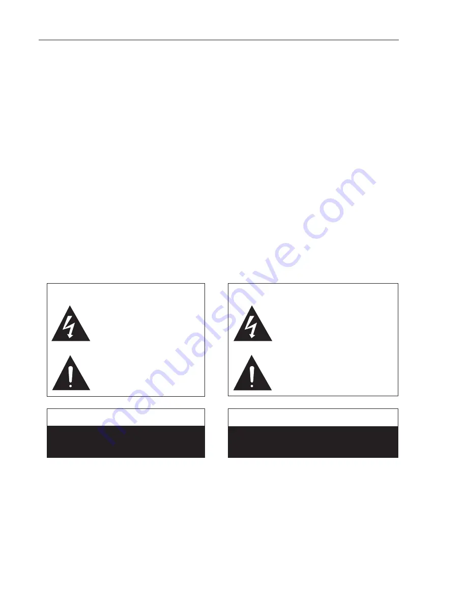
The lightning flash with arrowhead symbol,

within an equilateral triangle, is intended to

alert the use to the presence of uninsulated

"Dangerous Voltage" within the product's en-

closure that may be of sufficient magnitude

to constitute a risk of electric shock to hu-

mans.

The exclamanation point, within an equilateral

presence of important operating and mainte-

nance (servicing) instructions in the literature

accompanying the product.

VORSICHT

RISK OF ELECTRONIC SHOCK:

OPEN ONLY IF QUALIFIED AS

SERVICE PERSONNEL

GEFAHR EINES ELEKTRISCHEN SCHLAGES:

NUR VON QUALIFIZIEREM WARTUNGSPERSONAL

ZU ÖFFNEN

Der Blitz mit nach untenzielendem Pfeil in

einem gleichseitigen Dreieck weist den

Benutzer auf das Vorhandensein einer

unisolierten, "gefährlichen Spannung" im

Gehäuse hin, die stark genug sein kann, einer

Person einen gefährlichen elektrischen Schlag

zu versetzen.

Das Ausrufezeichen in einem gleichseitigen

Dreieck weist den Benutzer auf wichtige

Betriebs- und Wartungsvorschriften in den

beiliegenden Unterlagen des Gerätes hin.

Erklärung der graphischen Symbole

Explanation of Graphical Symbols

1. Read these instructions.

2. Keep these instructions.

3. Heed all warnings.

4. Follow all instructions

5. Do not use this apparatus near water. The apparatus shall not be

exposed to dripping or splashing and no objects filled with liquids,

such as vases, shall be placed on it.

6. Clean only with dry cloth.

7. Do not block any ventilation openings. Install in accordance with

the manufacturer’s instructions.

8. Do not install near any heat sources such as radiators, heat regis-

ters, stoves, or other apparatus (including amplifiers) that produce

heat.

9. Do not defeat the safety purpose of the polarized or grounding-type

plug. A polarized plug has two blades with one wider than the other.

A grounding type plug has two blades and a third grounding prong.

The wide blade or the third prong is provided for your safety. If the

provided plug does not fit into your outlet, consult an electrician for

replacement of the obsolete outlet.

10. Protect the power cord from being walked on or pinched particular-

ly at plugs, convenience receptacles, and the point where they exit

from the apparatus.

11. Make sure the power cord remains readily accessible at all times.

12. The AC Power Cord is the AC Mains disconnect.

13. Only use attachments/accessories specified by the manufactur-

er.

14. Disconnect this apparatus during lightning storms or when

unused for long periods of time.

15. Refer all servicing to qualified service personnel. Servicing is

required when the apparatus has been damaged in any way, such

as power-supply cord or plug is damaged, liquid has been spilled or

objects have fallen into the apparatus, the apparatus has been

exposed to rain or moisture, does not operate normally, or has been

dropped.

“WARNING - TO REDUCE THE RISK OF FIRE OR ELECTRIC

SHOCK, DO NOT EXPOSE THIS APPARATUS TO RAIN OR

MOISTURE”

“CAUTION: THESE SERVICING INSTRUCTIONS ARE FOR USE

BY QUALIFIED SERVICE PERSONNEL ONLY. TO REDUCE THE

RISK OF ELECTRIC SHOCK DO NOT PERFORM ANY SERVIC-

ING OTHER THAN THAT CONTAINED IN THE OPERATING

INSTRUCTIONS UNLESS YOU ARE QUALIFIED TO DO SO”.

IMPORTANT

Your Iconyx Steerable Column Loudspeaker contains no user-serviceable

parts and all service should be referred to qualified service personnel.

Summary of Contents for IC Live Fixed NON RHAON ICL-F

Page 1: ...IC Live Users Manual Models ICL F ICL F DUAL Owners Manual USERS MANUAL Assembly Installation Instructions ICL F ICL F DUAL IC Live...

Page 2: ...his apparatus near water The apparatus shall not be exposed to dripping or splashing and no objects filled with liquids such as vases shall be placed on it 6 Clean only with dry cloth 7 Do not block a...

Page 3: ...e Software 15 BeamWare 2 15 Canvas 29 Installation 32 Cabling Required 32 Power 32 Hardware Connections 33 Dimensions 34 Audio Digital Control 32 Installation 32 Wall Mounting 36 Suspended Flying 37 S...

Page 4: ...to assemble the ICL F DUAL is included in the cartons If you ordered a HK ICL series mounting hinge kit with your ICL F array the hinge hardware will be packed with the other hardware If you are not c...

Page 5: ...ly step is to remove the top of both modules To remove the top remove the eight machine screws from each side of the cabinet and lift the top and its mounting brackets out of the cabinet as shown The...

Page 6: ...rews supplied Make sure the connectors are fully seated You should hear a click when they seat If necessary use a flashlight to check because if the connectors are not seated properly you may have to...

Page 7: ...n it will be after the loudspeakers are installed 2 Remove the access plate and locate the Address switches Each 8 channel module will have an access plate Notice that there are 8 orange on off Dip sw...

Page 8: ...98 are not supported A typical system layout is shown below Notes 1 The audio cable is a conventional twisted pair shielded audio cable It terminates in a 3 pin Phoenix connector and loops from column...

Page 9: ...ibuted systems for balancing levels during final commissioning Inserting the Iconyx Software CD into the computer s CD ROM drive will open the splash menu screen shown below here INSTALLING THE USB TO...

Page 10: ...r has not passed Windows Logo testing with the fol lowing message Click on Continue Anyway Windows will finish the driver installation Click on Finish when prompt ed 4 Windows will now find another ha...

Page 11: ...fter Windows finds the appropriate driver you will be prompted to install it click on Next After Windows finishes installing the driver click Finish when prompted 4 Windows will now find another hardw...

Page 12: ...ng Manage Click on the Device Manager icon and look for USB to Serial Cable with a yellow exclamation mark You may find it under Universal Serial Bus Controllers Other Devices or Unknown Devices Doubl...

Page 13: ...0 or higher before proceeding You may down load NETFramework 2 0 from that same location on our website as the BeamWare 2 download or from Microsoft s download site http microsoft com downloads Click...

Page 14: ...n by clicking on Next C Select the Icon Option you wish to use and then click on Next to contin ue D Click on Install to begin the instal lation E Click on Done to complete the installation Notice tha...

Page 15: ...a floor plan A quick way to do this is to go to the Project pull down menu select Layout Presets and open the Preset folder Then choose one of the example floor plans For our purposes we ll use the f...

Page 16: ...r plan drawing and check the horizontal coverage Position the array by grabbing the yellow icon with your mouse cursor and moving it Clicking on the red box which identifies the aiming point allow you...

Page 17: ...ou added more than one array but didn t select one of them a Select Array prompt will list the arrays you inserted into the project under Layout and ask you to select one of them Note that you can als...

Page 18: ...t You should know the physical dimensions of the area s you want to cover so the next logical step is to set up the audience area s using the Audience Area section on the right side of the screen To s...

Page 19: ...d and its associated drop down menu One of the unique features of Iconyx steerable arrays is the ability to generate either single or multiple lobes We ll be discussing multiple lobes later in this tu...

Page 20: ...below was made using Medium Resolution You also have the opportunity to choose the simulation s Bandwidth its Center Frequency and its Weighting The Frequency section lets you select center frequencie...

Page 21: ...IC 16L you can select up to a maximum of 8 lobes It s up to four on the IC 8L For now select 2 to add a second beam to the graphic At first glance it may appear that nothing happened since the program...

Page 22: ...array isn t ideal You can override this warning if you want and the program will still attempt to properly focus all the beams You may however want to try moving the array up or down to see if you ca...

Page 23: ...ot that the beam opening was narrowed to 25o to obtain a longer throw The next graphic shows an even larger room one with a 125 foot throw Note that the opening angle was reduced to 20o Still the leve...

Page 24: ...setup screen that allows you to Export save the BeamWare 2 Setup as a rhs Setup file that can easily be imported into EASE and EASE JR It s a simple thing to do just open the EASE Iconyx DLL file int...

Page 25: ...from two ICL F Columns modules In BeamWare 2 these relationships are stored in the following manner every Column has a unique ID ICID number and every Array has a unique ID Array ID number When a col...

Page 26: ...termine what Columns are avail able Note that you may have to adjust the Columns in Network section of the window to see the entire listing The next step is to scan the network for Columns Arrays Hard...

Page 27: ...linked together The easiest way to assign one of the Columns to an Array is to grab it using the cursor and left mouse button and drag it to one of the Column icons Notice that the color of the Colum...

Page 28: ...work setup window and explore the two setup options we ignored earlier see page 35 The Scan for new Arrays on network option is similar to the Scan for Columns on network option except that it also id...

Page 29: ...ou also have a choice of initializing the column array to the default setting or of retrieving the column array s previous settings We recommend that you use Retrieve current settings from module sinc...

Page 30: ...High Pass Filter button inserts a high pass filter into the signal chain and allows you to dial in any low frequency roll off you desire It was preset to 100 Hz with a 24 dB per octave slope Please d...

Page 31: ...cluded in the program Pressing the Signal Generator but ton will bring up the following screen which allows you to choose the signal s frequency and distribute the signal to the column array Please no...

Page 32: ...the column s do not include a power on off switch and you will have to make sure an external power on off switch is provided Each module however does include a self restoring circuit breaker as protec...

Page 33: ...RX TX to TX and so on Recommended RS422 data wire type CAT5E wire is acceptable or for shielded type Belden 9729 has been tested by Renkus Heinz up to 800 meters When using long wire lengths a 120 Oh...

Page 34: ...Address Number Switches See Page 7 Audio Input Looping Connectors Push To Reset Circuit Breaker Power Connector Universal 100 to 240 Volts 50 60 Hz Signal Limiting Status LEDs See Page 7 Hardware Inp...

Page 35: ...Dimensions 44 1 4 112 5 cm 47 119 5 cm 95 241 5 cm 44 1 4 112 5 cm 8 20 cm 8 20 cm 7 17 8 cm 48 122 cm 35 IC Live Users Manual ICL F ICL F DUAL...

Page 36: ...e appropriate Com Port to connect the Fault Monitor to the network and press OK The Monitoring tab in the Options folder allows you to adjust the scan interval time from 5 seconds to 300 sec onds Use...

Page 37: ...The program checks each amplifier module and reports any failures such as loss of power It also checks the amplifiers operating temperature and reports any over temperature find ings If a fault is de...

Page 38: ...ither right or left swing away from the wall ICL F columns will have two hinge sec tions ICL F DUAL columns will have three hinge sections The female hinges should be attached to the column and the ma...

Page 39: ...make sure they are properly made Note The ICL F audio inputs comply with AES Standard 48 2005 on interconnecting grounding and shielding i e pin 1 is connected to chassis NOISE Most noise problems are...

Page 40: ...ic 7 22 Equipment Requirements 8 Exporting to EASE 24 F Fault Monitoring 36 37 Filters 30 H Hinges 36 I Installation Columns 38 Software 8 to 14 Level control 31 N NetFramework 8 13 Network Setup 25 S...

Page 41: ...ve down to 800 Hz ICL F DUAL 400 Hz when stacked Five 6 5 inch cone transducers with neodymium magnets Three 1 inch HF titanium nitride compression drivers 8 per module ICL F 48 H x 8 W x 7 D 121 5 cm...

Page 42: ...19201 Cook Street Foothill Ranch CA USA Phone 1 949 588 9997 Fax 1 949 588 9514 sales renkus heinz com www renkus heinz com RH 657 Rev B March 2010...

Reviews: