Installation guide
H-1000-5029-05-B
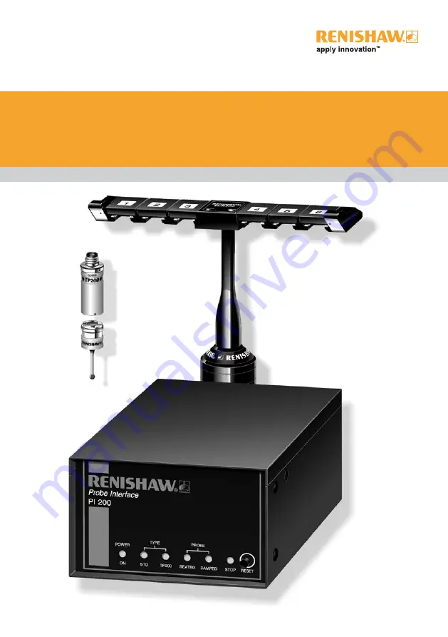
PI 200 interface for the TP200 system
Page 1: ...uy your excess underutilized and idle equipment along with credit for buybacks and trade ins Custom engineering so your equipment works exactly as you specify Critical and expedited services Leasing R...
Page 2: ...Installation guide H 1000 5029 05 B PI 200 interface for the TP200 system...
Page 3: ...effort has been made to ensure that the contents of this document are free from inaccuracies and omissions However Renishaw makes no warranties with respect to the contents of this document and speci...
Page 4: ...PI 200 interface for TP200 probe system installation guide...
Page 5: ...to cause harmful interference in which case you will be required to correct the interference at your own expense Information to user FCC section 15 21 The user is cautioned that any changes or modific...
Page 6: ...t must be obtained from Renishaw if non Renishaw equipment e g interfaces and or cabling is used or substituted Failure to comply with this will invalidate the Renishaw warranty Claims under warranty...
Page 7: ...owing conditions as defined in BS EN 61010 1 2001 Protection provided by enclosure IP30 Altitude Maximum 2000 m Operating temperature 0 C to 50 C Storage temperature 10 C to 70 C Relative humidity Max...
Page 8: ...robe polarity switch 21 3 Connector pin outs 22 3 1 PICS input connector 22 3 2 PICS output connector 23 3 3 Solid state relay SSR output connector 24 3 4 Stylus change rack SCR output connector 25 3...
Page 9: ...Contents 7 PICS terminations 40 8 Summary of changes from earlier versions 41 9 Maintenance 42 9 1 PI 200 42 9 2 TP200 probe and stylus module 42 9 3 SCR200 rack 42 10 Fault finding 43...
Page 10: ...n sensing techniques that provide better form measuring accuracy and operating life than can be achieved with kinematic switching probes The SCR200 stylus change rack provides storage for pre qualifie...
Page 11: ...Introduction TP200 probe sensor TP200 stylus module Stylus Kinematic coupling SCR200 stylus change rack PI 200 interface Figure 1 TP200 precision touch trigger probe system...
Page 12: ...whether the probe is a kinematic switching probe TP20 TP6 TP2 type or a TP200 and automatically selects the appropriate operating mode When using the SCR200 change rack to perform automatic stylus ch...
Page 13: ...is provided on the PICS port HALT will be asserted if the probe current remains greater than trigger level 2 for a pre set delay time determined by the settings of configuration switches 11 and 12 The...
Page 14: ...tch 6 and switch 7 Delay time set by switch 11 and switch 12 SYNC HALT Figure 2 SYNC and HALT signal timing for a TP200 gauge point Figure 3 SYNC and HALT signal timing for a gauge point when a kinema...
Page 15: ...er to the section configuration switches for more information on the debounce options The adaptive settings ensure that combinations of CMM vibration and large stylus assemblies do not cause a false i...
Page 16: ...me delay selected by switches 11 and 12 as indicated in figure 5 NOTE The probe cannot take accurate points when damped mode is active and the CMM controller must clear the PDAMP signal to return the...
Page 17: ...compensation is switched off If the stylus remains deflected for longer than 10 seconds drift of the zero reference may occur The audible warning will sound after this period to indicate that the prob...
Page 18: ...Front panel indicators Indicator Colour Function POWER ON Green Mains power on TYPE STD Green Kinematic probe selected TP200 Green TP200 probe selected PROBE SEATED Green ON probe armed seated OFF pro...
Page 19: ...be disabled by configuration switch 5 2 To warn by a continuous tone that the stylus has remained deflected for longer than 10 seconds The alarm can be cleared by operation of the RESET button on the...
Page 20: ...active LOW 2 Head LED control UP DOWN External control via PICS LED mimics SYNC 3 STOP disabled UP DOWN PI 200 ignores PICS STOP STOP asserts HALT SYNC 4 SYNC polarity UP DOWN SYNC HIGH and SSR closes...
Page 21: ...tputs Switch 5 When enabled a tone will sound for approximately 160 milliseconds when the probe triggers and SYNC is asserted When disabled the tone will activate only when the stylus has remained def...
Page 22: ...bounce options Trigger level Probe signal V t Switch 6 Down Switch 7 Down SYNC SYNC SYNC SYNC 20 ms 20 ms adaptive 100 ms 100 ms adaptive 20 ms 20 ms 100 ms 80 ms Switch 6 Up Switch 7 Down Switch 6 Do...
Page 23: ...obe damped mode is set from being falsely asserted when the probe is subjected to vibration a time delay filter is applied Refer to the description in trigger confirmation signal HALT section If a col...
Page 24: ...hat the centre contact of the M8 connector is positive and the thread is ground 0 V A reversed polarity connection will cause the POWER and STOP indicators to be illuminated on the front panel Sliding...
Page 25: ...in numbers are illustrated in figure 9 and their functions are shown in table 4 9 8 7 6 5 4 3 2 1 Figure 9 PICS input connector pin numbers Table 4 PICS input connector Pin number Description 1 STOP 2...
Page 26: ...output connector Pin number Description 1 STOP 2 PPOFF 3 Ground 0 V 4 Reserved 5 SYNC 6 HALT 7 PDAMP 8 LEDOFF 9 Not used Shell Screen 3 2 PICS output connector The PICS output connector is a 9 pin D...
Page 27: ...s a 7 pin DIN socket The pin numbers are illustrated in figure 11 and their functions are shown in table 6 7 6 3 1 5 4 2 Figure 11 SSR output connector view on rear panel Table 6 SSR output connector...
Page 28: ...eve the same effect as the RESET button on the front panel of the PI 200 interface Such a facility may be useful if manual stylus changing is to be frequently used or if the PI 200 is difficult for th...
Page 29: ...1 3 rack wide x 2U high 140 mm x 88 mm x 183 mm deep Weight 1 25 kg Mounting method 19 in rack or freestanding Mounting screws M5 x 8 mm maximum penetration Probe voltage open circuit 12 4 V Probe cab...
Page 30: ...sensor Stylus module standard or low force Tools cleaning kit Test certificate User s guide Stylus module standard force A 1207 0010 Stylus module low force A 1207 0011 Stylus change rack kit standar...
Page 31: ...s PS2R A 5000 3603 Rubber feet for PI 200 P FE01 0003 5 2 Accessories Refer to Probing systems for coordinate measuring machines Renishaw part number H 1000 5050 for details of the available range of...
Page 32: ...roller as indicated in figures 13 and 14 POWER TYPE PROBE RESET ON STD TP200 SEATED DAMPED STOP PROBE INTERFACE R Figure 13 Mounting the PI 200 To mount the PI 200 as indicated in figure 13 requires 2...
Page 33: ...units To fit the PI 200 into an existing installation adjacent to an older style PHC10 or ACC2 with extruded aluminium side panels a link bracket part no M 1018 0097 and 2 M5 6 mm long screws part no...
Page 34: ...in figures 16 21 The standard interconnection cables are listed in table 8 Contact Renishaw for other cable lengths cable specification or special configurations Consult the appropriate product insta...
Page 35: ...tion MIH head Cable 2 Cable 1 MIH TP200 PI 200 PICS output CMM controller PAA1 adaptor Figure 18 System interconnection PH10T head Cable 4 Cable 3 SCR200 TP200 PI 200 Communications to CMM controller...
Page 36: ...S232 1 11 14 HCU 15 18 OUTPUT 10 Installation procedure Figure 19 System interconnection PH10M head Cable 4 Cable 3 SCR200 TP200 PI 200 Communications to CMM controller PH10M PHC10 2 PICS output CMM c...
Page 37: ...nection SP600M scanning probe and autochange Cable 4 Cable 3 AC2 PI 200 Communications to CMM controller PH10M PHC10 2 PICS output CMM controller Cable 7 To ACR1 rack PAA1 adaptor SP600M Cable 8 Cable...
Page 38: ...ection TP7M touch trigger probe and autochange Cable 4 Cable 3 PI 7 2 Communications to CMM controller PH10M PHC10 2 PICS output CMM controller Cable 7 To ACR1 rack PAA1 adaptor Cable 8 Cable 5 ACC2 2...
Page 39: ...nal PDAMP on the PICS port when the probe is approaching the rack to prevent a false trigger being generated when the probe contacts the docking port lid If this is not possible a shock absorbing pad...
Page 40: ...to table 8 cable number 12 For applications requiring two racks a dual rack splitter cable is needed Refer to table 8 cable number 11 and figure 23 The dual SCR200 adaptor cable must be fitted at the...
Page 41: ...80 1 60 A 1016 7673 Coiled PL12 0 10 A 1016 7674 Plain PL13 0 10 0 20 A 1016 7675 Coiled 4 PLM6 6 A 1016 7564 Unterminated one end PLM7 4 A 1016 7563 Unterminated one end PLM8 6 A 1016 7677 PLM9 4 A...
Page 42: ...c switching probes TP1 TP2 TP6 is present it must be removed The signal wire resistance must be less than 5 ohms per conductor Some experimentation with typical stylus arrangements may be necessary to...
Page 43: ...nector ports Refer to figures 16 21 in the section system interconnection for examples of the PICS connections for typical installations Note that the order in which the system components are connecte...
Page 44: ...ly and 5 V to 15 V dc dc converter Functionality identical A 1207 0050 09 V10 Withdrawn A 1207 0050 08 V9 Additional PDAMP filter delay time option 2 0 ms and 7 5 ms added Switches 11 and 12 coded to...
Page 45: ...cision ball V groove seatings The coupling mechanism has been tested in a wide range of environments and is highly tolerant of non metallic dust but regular inspection and cleaning with the material s...
Page 46: ...11 The probe fails to trigger and the probe LEDs glow only dimly when the stylus touches the workpiece but the probe operates normally when the stylus is deflected by hand PI 200 indicators SEATED LED...
Page 47: ...remedies The probe sensor is faulty The probe is loose in the probe head There is excessive vibration from an external source There is excessive vibration from the CMM Remove the probe and test by su...
Page 48: ...ation from the CMM The traverse speed is too high Use stylus arrangements within recommendations Check the CMM s air supply Maintain the CMM s air bearing system Reduce the traverse speed Table 17 The...
Page 49: ...nts within recommendations Check the stylus joints Ensure the module is correctly seated and the probe is tight in the probe head Inspect and clean the kinematic coupling Requalify the stylus tips Tab...
Page 50: ......
Page 51: ...under Edge Gloucestershire GL12 8JR United Kingdom T 44 0 1453 524524 F 44 0 1453 524901 E uk renishaw com www renishaw com H 1000 5029 05 B For worldwide contact details please visit our main websit...
Page 52: ...uipment Have surplus equipment taking up shelf space We ll give it a new home Learn more Visit us at artisantg com for more info on price quotes drivers technical specifications manuals and documentat...