252
Chapter 5 Interrupt
5.3 Interrupt Sequence
An interrupt sequence — what are performed over a period from the instant an interrupt is accepted to the
instant the interrupt routine is executed — is described here.
If an interrupt occurs during execution of an instruction, the processor determines its priority when the
execution of the instruction is completed, and transfers control to the interrupt sequence from the next
cycle. If an interrupt occurs during execution of either the SMOVB, SMOVF, SSTR or RMPA instruction,
the processor temporarily suspends the instruction being executed, and transfers control to the interrupt
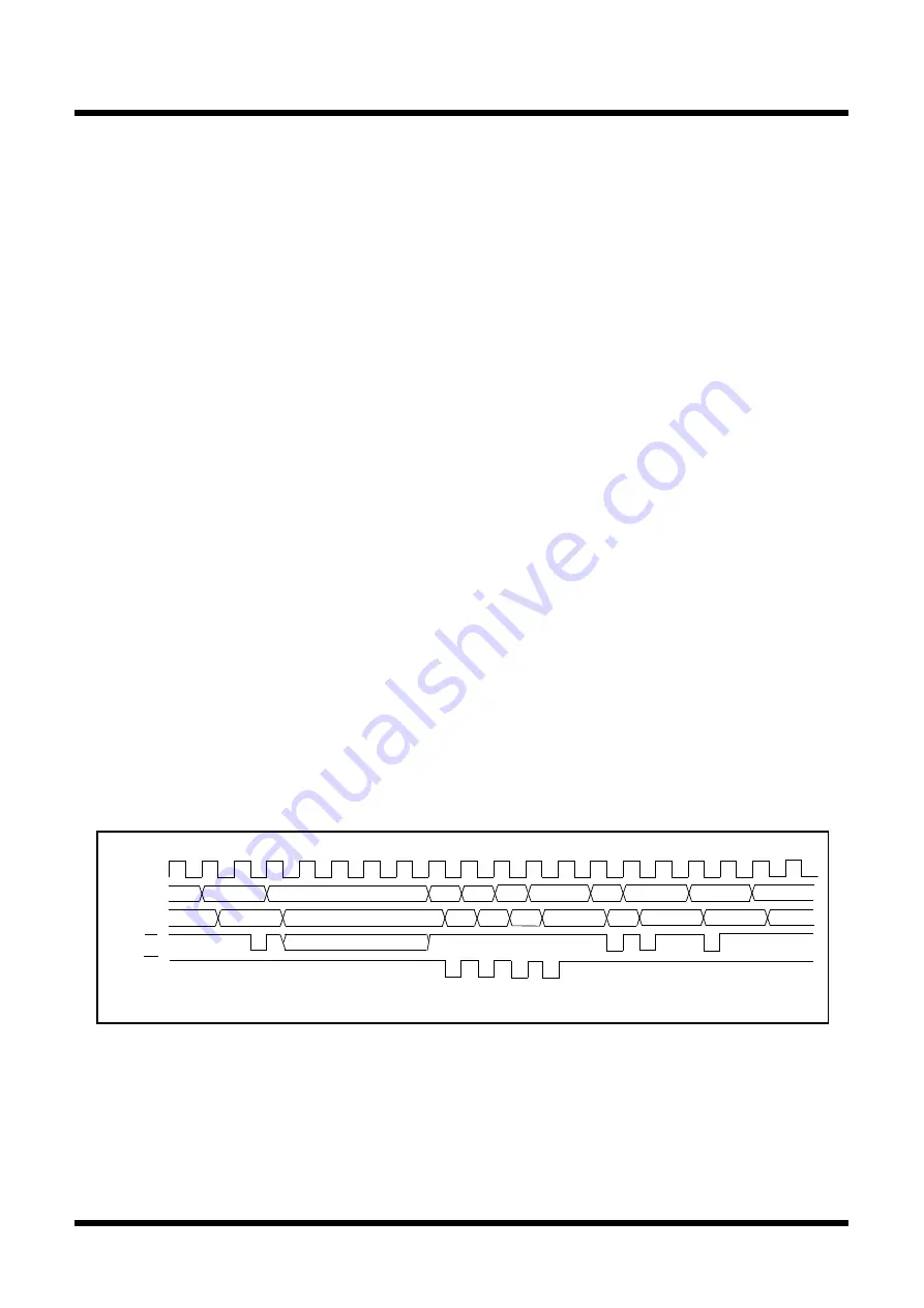
sequence. Figure 5.3.1 shows the interrupt sequence executing time.
In the interrupt sequence, the processor carries out the following in sequence given:
(1) CPU gets the interrupt information (the interrupt number and interrupt request level) by reading address
00000
16
. Then, the IR bit of corresponding interrupt is set to 0 (no interrupt request issued).
(2) Saves the FLG register as it was immediately before the start of interrupt sequence in the temporary
register (Note 1) within the CPU.
(3) The I flag, the D flag, and the U flag of the FLG register are as follows:
• The I flag is set to 0 (interrupt disabled)
• The D flag is set to 0 (single-step interrupt is disabled)
•The U flag is set to 0 (ISP is specified)
However, the U flag does not change when the INT instruction of the software interrupt numbers 32-63 is
executed.
(4) Saves the temporary register (Note 1) within the CPU in the stack area.
(5) Saves the PC in the stack area.
(6) Sets the interrupt priority level of the accepted instruction in the IPL.
(7) The first address of the interrupt routine set to the interrupt vector is set to the PC.
After the interrupt sequence is completed, the processor resumes executing instructions from the first ad-
dress of the interrupt routine.
Note 1: This register cannot be utilized by the user.
5.3 Interrupt Sequence
Figure 5.3.1 Interrupt sequence executing time
1
2
3
4
5
6
7
8
9
1
0
1
1
A
d
d
r
e
s
s
0
0
0
0
0
1
6
Undefined
SP-2
U
n
d
e
f
i
n
e
d
Interrupt
information
Undefined
1
2
1
3
14
1
5
1
6
1
7
1
8
C
P
U
c
l
o
c
k
Address bus
D
a
t
a
b
u
s
W
R
R
D
S
P
-
1
S
P
-
4
S
P
-
3
SP-2
contents
SP-1
contents
S
P
-
4
c
o
n
t
e
n
t
s
SP-3
contents
V
E
C
VEC+1
V
E
C
+
2
1
9
2
0
P
C
V
E
C
c
o
n
t
e
n
t
s
VEC+1
contents
V
E
C
+
2
c
o
n
t
e
n
t
s
N
o
t
e
:
U
n
d
e
f
i
n
e
d
p
a
r
t
s
d
i
f
f
e
r
a
c
c
o
r
d
i
n
g
t
o
t
h
e
s
t
a
t
e
s
o
f
t
h
e
q
u
e
b
u
f
f
e
r
.
I
f
t
h
e
q
u
e
b
u
f
f
e
r
i
s
i
n
t
h
e
s
t
a
t
e
w
h
e
r
e
a
n
i
n
s
t
r
u
c
t
i
o
n
c
a
n
b
e
t
a
k
e
n
,
a
r
e
a
d
c
y
c
l
e
i
s
g
e
n
e
r
a
t
e
d
.
Summary of Contents for R8C/Tiny Series
Page 50: ...Chapter 3 Functions 3 1 Guide to This Chapter 3 2 Functions...
Page 151: ...134 Chapter 3 Functions 3 2 Functions Blank for page layout...
Page 278: ...Chapter 6 Calculation Number of Cycles 6 1 Instruction queue buffer...
Page 297: ...R8C Tiny Series Software Manual 2 6 2 Ote machi Chiyoda ku Tokyo 100 0004 Japan...


