background image


Introduction 

 
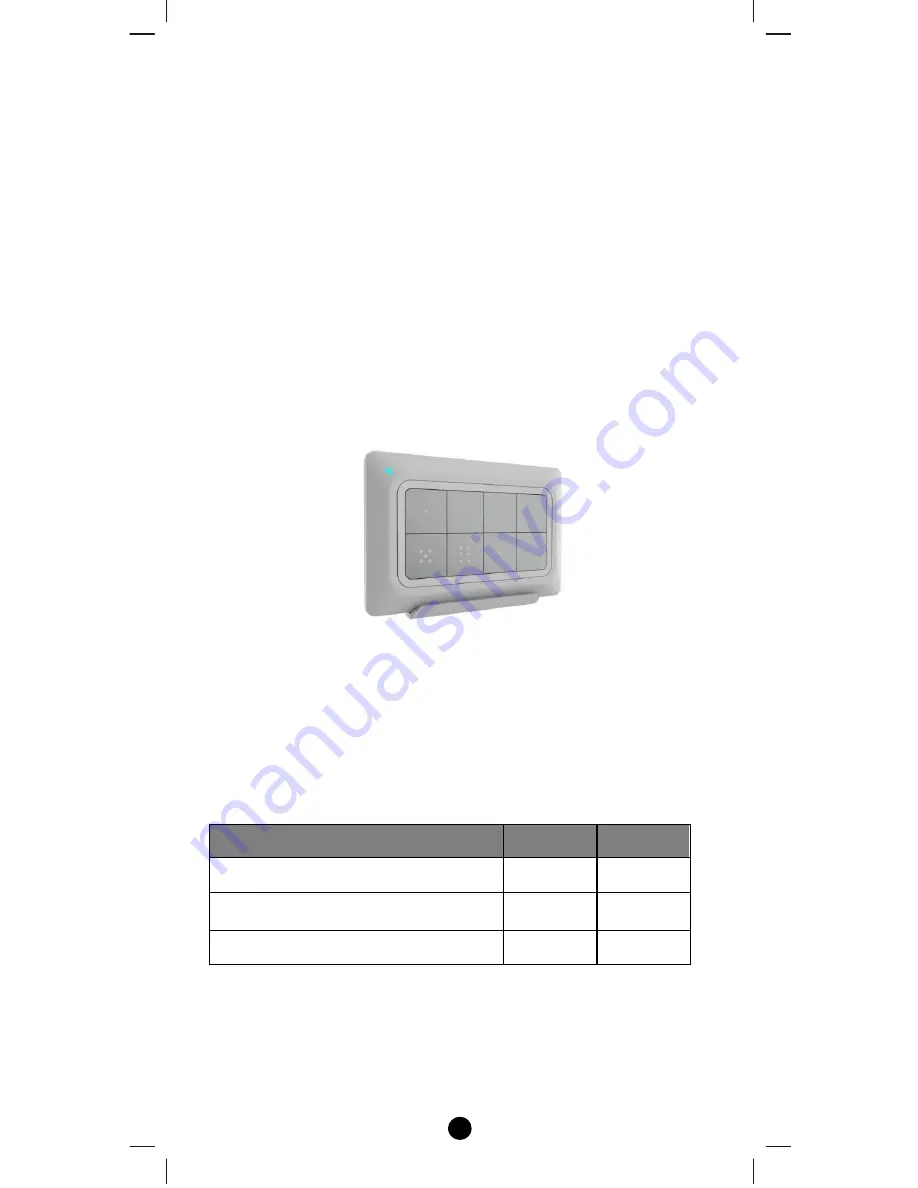
The ZRC-90 Scene Master (Figure 1) is a Z-Wave Central Scene 
Controller. When one of the buttons on the ZRC-90 is pushed, your Z-
Wave central controller will receive a signal which it can use to trigger 
unlimited control possibilities. With 8 buttons, each supporting a long-
press capability, you can control 16 different actions in your central 
controller. The ZRC-90 is a great solution for triggering events more 
quickly than taking out your smart-phone and running a home control 
App.  The Scene Master is ideal for kids, elderlies and guests who may 
not have full access to your smart home’s mobile application and 
hence may not have the rights to switch on various lighting, heating, 
air conditioning and other home appliance.  With a convenient snap-in 
wall mount, the ZRC-90 can also be removed to keep it handy while 
you go about your home for the ultimate in simple convenience. 


Figure 1   ZRC-90 


Gateway Requirements 

 
Please make sure your gateway supports below functions before use 
ZRC-90. 

Z-Wave Command Class


Controlled   Supported 

Association command class 

Association Group Information (AGI) 
command class 

Central Scene command class 


Summary of Contents for ZRC-90 Scene Master

Page 1: ...1 ZRC 90 Scene Master Operating Instructions Master your home Master your life ...

Page 2: ... a home control App The Scene Master is ideal for kids elderlies and guests who may not have full access to your smart home s mobile application and hence may not have the rights to switch on various lighting heating air conditioning and other home appliance With a convenient snap in wall mount the ZRC 90 can also be removed to keep it handy while you go about your home for the ultimate in simple ...

Page 3: ...imary and secondary controllers operating on the same system A Z Wave network has its own unique ID code so that controllers not in the network cannot control the system Scene A collection of Z Wave devices configured to turn to a specific level setting mode or perform an operation Scenes are usually activated by a controller timed event or specific conditions Primary Controller The first controll...

Page 4: ...network To avoid inconsistency all node ID allocations are maintained by the SIS Inclusion Controller The SIS enables other controllers to include exclude nodes to from the network When SIS functionality is enabled the controller also takes the role as the Primary Controller because it has both latest network topology and allocated node IDs All the other controllers are called Inclusion Controller...

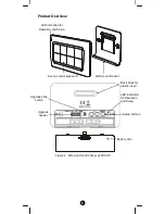
Page 5: ...d control keys of ZRC 90 LED indication for Operation and Setup Wall mount bracket Scene control keyboard Setup buttons Upgrade header Upgrade slide switch Battery door Back block for plastic insert LED indication for Operation and Setup ...

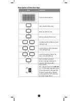
Page 6: ...D light up Create Primary Press the keys until LED light up Create Secondary Press the keys until LED light up Reset to factory default Press and keep holding 10 seconds then triple click Slide switch OP Normal operation default PC PC firmware upgrade mode The slide switch is designed for firmware upgrade by supplier please switch to OP direction for normal operation ...

Page 7: ...rough the following sections of this user manual and store for future reference ZRC 90 can be included and operated in any Z Wave network with other Z Wave certified devices from other manufacturers and or other applications All non battery operated devices within the network will act as repeaters regardless of vendor to increase reliability of the network ZRC 90 can act as a secondary Central Sce...

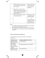
Page 8: ...f if the command or operation is invalid Notes 1 If the device already existed into the network the unit will exit Learn mode automatically after 5 seconds 2 If the device does not exist into the network and no command from gateway the unit will exit Learn mode automatically after 30 seconds Scene activation and deactivation The real actions of scene will be depended on each gateway interpretation...

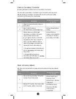
Page 9: ...istening mode by click once on W button LED will keep flashes slowly 2 Listening mode will exit automatically after 30 seconds of inactivity LED stay off Notes 1 The mode must not be exited during communication process with another controller Please wait for entire communication process to be completed 2 It is not allowed to enter any user input from the remote s hard key after entry this mode ZRC...

Page 10: ...etwork 3 In a Z Wave network only the primary controller or inclusion controller can add or include devices into its network If ZRC 90 is configured as a secondary controller it will report Error if users attempt to use ZRC 90 to add a device into its network 4 If no ACK signal received for more than 30 seconds the Add Device mode will exit automatically Removing Device from the Network Step Setup...

Page 11: ...ller and ZRC 90 will act as a secondary controller This primary shift is done by following the steps below Step Setup Key Setup LED Indication on ZRC 90 1 Place the two controllers close to each other 2 Press W L buttons simultaneously until LED light up LED will keep flashes slowly 3 Please make sure the target primary controller is setup to receive information mode e g target primary controller ...

Page 12: ...he Learn mode if this is a another ZRC 90 Please refer to the target controller user manual for more information Target secondary controller will act as a secondary controller after this action Original ZRC 90 primary controller will still keep in a primary controller after this action LED will flashes slowly until complete the step of Create a Secondary Controller Reset to factory default ZRC 90 ...

Page 13: ...r electrical shock Do not mount to locations subject to high temperatures high humidity or exposure to water Doing so could cause a fire or electrical shock Do not mount to locations subject to large amounts of vibration large jolts or large forces These could cause an injury if the unit falls and breaks MOUNTING PROCEDURE PRECAUTIONS Do not modify parts or use the unit in ways other than its inte...

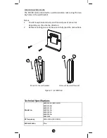
Page 14: ... transmit power are varies depending on the antenna direction 2 Before mounting to a wall be sure to fully read the precautions Mount to the wall bracket Dismount from wall bracket Figure 3 Installation Technical Specifications Model no BW8510US ZRC 90US BW8510NA BW8511US BW8511NA BW8500US BW8500NA RMZ3103 RF frequency 908 42MHz ZRC 90US LED indication Blue ...

Page 15: ... cover of the packing box check that the following accessories are included ZRC 90 Scene Master Plastic insert Wall mount bracket Wall anchor x 2pcs Screw x 2pcs User Manual Warranty sheet Scene label sheet Scene Reference List Scene Button Action in single click Action in double click Remark 1 2 3 4 5 6 7 8 Please write down the scene action in case you need further reference in the future Wirele...

Page 16: ...ser serviceable parts FCC Notice This device complies with Part 15 of the FCC rules Operation is subject to the following two conditions 1 this device may not cause harmful interference and 2 this device must accept any interference received including interference that may cause undesired operation Note This equipment has been tested and found to comply with the limits for a Class B digital device...

Page 17: ...sk of electrical shock Risk of burns Do not dispose of electrical appliances and unsorted municipal waste use separate collection facilities Contact your local government for information regarding the collection systems available There is no user serviceable parts in this unit Use only power supplies listed in the user instructions Caution Risk of explosion if battery is replaced by an incorrect t...

Reviews: