35
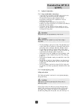
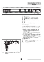
The CAN-bus route on one skid is as follows:
Several nodes on the CAN-bus, several CAN-OT interfaces
and several heat pumps. The CAN-bus cables for the heat
pumps and for the CAN-OT interfaces are connected in the
general electrical panel (GEP). The maximum number of heat
SXPSVRQRQHVNLGLV¿YH
see Fig. 25
)
.
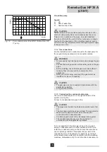
The CAN-bus route for several skids is as follows:
Several nodes on the CAN-bus, several CAN-OT interfaces
and several heat pumps. The CAN-bus cable for the CAN-OT
LQWHUIDFHVLVFRQQHFWHGWRWKH¿UVWJHQHUDOHOHFWULFDOSDQHO
*(37KHODVWKHDWSXPSRQDVNLGWKLVLVFRQ¿JXUHGDV
an intermediate node) is connected with a CAN-bus cable to
the general electrical panel for the next skid. The maximum
number of heat pumps is 16. (
See Fig. 26
)
.
m
CAUTION
The OpenTherm bus only allows point-to-point connections.
Legend
1 Heat
pump
2 CAN-OT
Interface
3
General switch box (GEP)
4
OT cascade controller
5 Outside
6 Inside
Legend
1 Heat
pump
2 CAN-OT
Interface
3
General switch box (GEP)
4
OT cascade controller
5 Outside
6 Inside
u
Unit becomes intermediate node
7.5.1 Introduction to the CAN-bus
m
CAUTION
The heat pumps on the skids are already connected to the
CAN-bus cable on delivery and have a CAN-bus address.
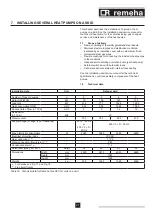
The CAN-bus cable must comply with the Honeywell SDS
standard. The table below shows details for a number of CAN-
bus cable types, grouped according to the maximum distance
for each cable type.
T004287-B
3
1
2
2
4
2
5
6
1
1
CAN
CAN
CAN
CAN
CAN
OT
OT
OT
Fig. 25
CAN-bus with one skid
T004288-B
CAN
CAN
CAN
CAN
CAN
3
3
1
2
2
4
2
5
6
1
1
CAN
CAN
1
1
1
CAN
CAN
OT
OT
OT
2
2
2
OT
OT
OT
u
Fig. 26
CAN-bus with several skids

