background image

9

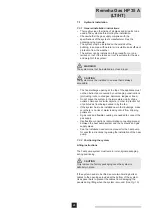
4.2.1 Buffer 

vessel

$EXIIHUYHVVHOLVQRWVSHFL¿FDOO\UHTXLUHG,IWKHV\VWHPGRHV

QRWKDYHVXI¿FLHQWFDSDFLW\DEXIIHUYHVVHOFDQEHEXLOWLQWRWKH

system. The buffer vessel acts as a thermal energy battery, 
reducing the number of starts for the heat pumps. Too many 

VWDUWVLQDVKRUWSHULRGRIWLPHUHGXFHWKHDYHUDJHHI¿FLHQF\RI

the heat pumps.
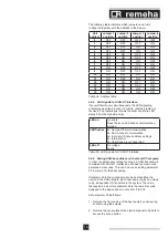
The volume of the buffer vessel (in litres) can be found in the 
table below.

Number of Gas HP units

Effective volume* of buffer 

vessel in l

1

300

2

500

3

800

4

1000

5

1000

 (IIHFWLYHYROXPH YROXPHEHWZHHQÀRZDQGUHWXUQ

connections on the buffer vessel

Table 01  Buffer vessel volume

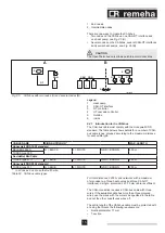
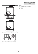
Legend

1 Air 

vent

2 Lifting 

eye

+HDWSXPSÀRZ

4 Temperature 

recorder

5 Temperature 

recorder

6 Temperature 

recorder

7 Temperature 

recorder

8 Temperature 

recorders

Heat pump return

10 Draining 

outlet

11 

Separation plate (perforated)

&HQWUDOKHDWLQJV\VWHPÀRZ

13 Effective 

volume

14 

Central heating system return

4.3 Hydraulic 

diagrams 

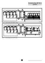
The following examples only give a broad outline of the 
principle of heat production.

m

CAUTION 

It is important for both the central heating boilers and the heat 

SXPSVWKDWWKHFRQ¿JXUDWLRQRIWKHKHDWWUDQVIHUHOHPHQWLV
SDUWRIWKHK\GUDXOLFGHVLJQVLQFHHI¿FLHQF\LQFUHDVHVLIWKH

system is set correctly for both the hydraulics and controls.

T003992-A

1

2

3

9

14

12

11

11

13

8

5

6

10

7

4

Fig. 01 

Schematic drawing of the buffer vessel

Summary of Contents for Gas HP 35 A HT

Page 1: ...Heat pump EN United Kingdom After Sales Service guide Gas HP 35 A LT HT renewable technologies ...

Page 2: ...pipe 14 6 3 Electrical connections and control general 14 6 3 1 Connecting to the main power supply 14 6 3 2 Controlling the heat pumps via a 0 10 V signal 14 6 3 3 Controlling the heat pumps via an On Off signal 14 6 3 4 Connecting a water circulation pump 14 6 4 Electrical connections and control OpenTherm 14 6 4 1 Introduction to the CAN bus 15 6 4 2 Connecting the CAN bus to the Gas HP heat pu...

Page 3: ...Remeha OpenTherm controller 42 7 5 8 Connecting a water circulation pump 42 7 5 9 Controlling the heat pumps via a 0 10 V signal 42 7 6 Connection options for the 0 10 V control PCB IF 01 43 7 6 1 Connection status Nc 43 7 6 2 Connection OTm 43 7 6 3 Analogue input 0 10 V 43 7 6 4 Analogue control based on temperature 43 7 6 5 Analogue control based on heat output 43 7 6 6 Analogue output 0 10 V 4...

Page 4: ...important information 1 2 Terms and abbreviations GEP switch box for the appliance marked with MAIN where necessary SWW domestic hot water Skid heating unit consisting of one general switch box 3 DQG WZR WR YH LQGLYLGXDO JDV DEVRUSWLRQ KHDW SXPSV that are connected to one another beforehand for gas central heating and electricity and linked to one another by supporting beams 1 3 Liability 1 3 1 Ma...

Page 5: ...ons for the appliance found in the accompanying manuals 5HTXHVW WKH DVVLVWDQFH RI D TXDOL HG LQVWDOOHU IRU WKH installation Ask Remeha to perform initial commissioning of the appliance Ask the installer to explain the installation Ensure that the necessary checks and maintenance work are carried out Keep the manuals in good condition and near to the appliance This appliance must not be used by peo...

Page 6: ...Do not carry out any work on the closed cooling circuit or on the valves m DANGER If you smell ammonia 1 Turn off the device 2 Keep your distance and avoid inhaling ammonia fumes 3 Do not carry out any work on the closed cooling circuit RXUVHOI EXW OHDYH WKLV WR D TXDOL HG LQVWDOOHU 2 2 Recommendations m WARNING Installation and maintenance of the appliance must be FDUULHG RXW E D TXDOL HG LQVWDOO...

Page 7: ...7 The technical data for the heat pump can be found in the Installation and service manual for the heat pump 3 TECHNICAL DESCRIPTION ...

Page 8: ...rn temperature of the system is lower than 55 C back up boilers are not needed for low outside temperatures The output ratio between the heat pumps and the extra boilers can be determined based on the limiting investment on the one hand and the average HI FLHQFLHV RQ WKH RWKHU When the design return temperature of the system is higher than 55 C back up boilers are needed for low outside temperatur...

Page 9: ...le 01 Buffer vessel volume Legend 1 Air vent 2 Lifting eye HDW SXPS ÀRZ 4 Temperature recorder 5 Temperature recorder 6 Temperature recorder 7 Temperature recorder 8 Temperature recorders 9 Heat pump return 10 Draining outlet 11 Separation plate perforated HQWUDO KHDWLQJ V VWHP ÀRZ 13 Effective volume 14 Central heating system return 4 3 Hydraulic diagrams The following examples only give a broad ...

Page 10: ...Remeha Gas HP 35 A LT HT 10 T004284 A Fig 02 Hydraulic diagram with Quinta Pro boilers T004285 B Fig 03 Hydraulic diagram with Gas 310 boilers ...

Page 11: ... control is possible under certain conditions Contact our Sales Support department about this I OOHU RWKHU WKDQ D JO FRO PL WXUH LV XVHG WKH LQVWDOOHU himself must provide better insulation and an electric frost protection cable This also includes the pipe work supplied with the skid The pipe work on the accompanying skid has limited insulation it is up to the installer to provide better insulatio...

Page 12: ...uctural engineer for advice He will also be able to give advice on how to prevent structure borne noise being carried to any living areas 9LEUDWLRQ GDPSHUV PXVW EH WWHG EHWZHHQ WKH KHDW pumps and the support construction Standard dampers are available as an option Any customised work must be carried out in consultation with a noise expert The XQGHUO LQJ VWUXFWXUH PXVW EH VXI FLHQWO ULJLG 7KH KHDW ...

Page 13: ... the HYDSRUDWRU Q WKH PHDQWLPH WKH PDLQ DPPRQLD ÀRZ FRQWLQXHV to supply heat to the central heating water Experience has shown that no more than 50 defrosting cycles are needed during a normal winter A cycle only lasts an average of 3 minutes thanks to the high condensation WHPSHUDWXUH RI WKH DPPRQLD ÀRZ V D UHVXOW WKH GHIURVWLQJ F FOH KDV QR PHDVXUDEOH HIIHFW RQ WKH HI FLHQF RI WKH Remeha heat pu...

Page 14: ...section 7 5 9 for an explanation of how the interface works 6 3 3 Controlling the heat pumps via an On Off signal The heat pumps can be controlled via one On Off signal per unit See the Installation and service manual for the heat pump for the correct connections 6 3 4 Connecting a water circulation pump Each heat pump unit can control its own circulation pump See the Installation and service manu...

Page 15: ...s e g three heat pumps and three CAN OT LQWHUIDFHV D VLQJOH SURWHFWHG PP FDEOH LV VXI FLHQW The CAN connection requires a CAN bus cable with three wires If the available cable has more than three coloured ZLUHV XVH WKH ZLUHV ZLWK WKH FRORXUV DV VSHFL HG LQ WKH WDEOH DQG FXW WKH RWKHU VXSHUÀXRXV ZLUHV RII The entire length of the CAN bus cable must be protected with a casing that meets the followin...

Page 16: ...icken the cable by wrapping insulation tape around the cable casing next to the stripped section up to a diameter of approx 12 13 mm 4 Pull the shield back over the cable casing and use insulation tape to fasten the end of the shield that has been pulled back see Fig 06 A 5 If the heat pump is an end node in the network connect the three coloured wires to the orange connector as shown for D in Fig...

Page 17: ... by pressing the top of the cover and carefully pulling it forward 2 The jumpers on the CAN OT interface must be set as indicated in Fig 07 The CAN OT interface is an end node 3 Cut off a piece of cable that is long enough for the connection without any loops forming 4 Remove approximately 20 mm of the cable casing and the wires within it Make sure you do not cut into the cable protection plaited ...

Page 18: ...umps 1 2 are intermediate nodes CAN OT interface 0 and heat pump 0 are end nodes T003991 C OT On off OT H CAN CAN OT 2 2 S61 P8 P8 P8 X2 X1 A A A H L L 0 0 S S Mains N N L L OT On off OT H CAN CAN OT 1 1 S61 X2 X1 H L L 0 0 S S Mains N N L L OT On off OT H CAN CAN OT 0 0 S61 X2 X1 H L L 0 0 S S Mains N N L L GND L H GND L H GND L L H Fig 08 Connections on the CAN OpenTherm interface and Gas HP pri...

Page 19: ...munication working ÀDVKHV 2x No OpenTherm communication 3x No CAN bus communication 4x Incorrect CAN bus address settings 5x Internal error 6x CAN device is not supported LED off No voltage Faulty Table 05 LED signals for CAN OT interface 6 4 6 Setting CAN bus address on the Gas HP heat pump In order to operate several heat pumps in a CAN bus network combined with CAN OT interfaces each heat pump ...

Page 20: ... FRQ UP 5HSHDW WKLV XQWLO RX KDYH entered the full access code 8 5RWDWH WKH EXWWRQ WR SDUDPHWHU DQG SUHVV WR FRQ UP Now enter the CAN bus address for the heat pump Rotate the button to the number to be entered and press to FRQ UP 5HSHDW WKLV DFWLRQ XQWLO WKH FRPSOHWH DGGUHVV KDV been entered 9 Go to menu E and press the button to leave the control menus 10 Replace the cover plate for the switch bo...

Page 21: ...l VSHFL FDWLRQV FRQWURO DQG VDIHW FRPSRQHQWV RI WKH KHDW pumps 7 2 Technical data Installation data Unit Data per skid Number of Gas HP pumps n 2 3 4 5 Output A7 W50 kW 70 105 140 175 Load Hi kW 51 4 77 1 102 8 128 5 Gas consumption G25 m3 h 6 32 9 48 12 64 15 80 1RPLQDO UDWH RI ÀRZ 7 m3 h 6 9 12 15 Residual lift 7 kPa 20 Water content l 15 5 23 7 32 2 41 5 Supply voltage voltage type frequency 23...

Page 22: ...WHG DV FRQQHFWLRQ ò 8S ORZ S 5HWXUQ T004109 A 1245 622 245 378 133 G Up Ip 255 92 132 1400 1650 1245 100 100 1045 Fig 09 RQQHFWLRQ VLGH RI WKH FRQ JXUDWLRQ ZLWK PRXQWLQJ points for the vibration dampers T004110 A Fig 10 7RS RI WKH FRQ JXUDWLRQ ZLWK WZR KHDW SXPSV ...

Page 23: ... SXPSV T004106 A 1554 3610 1554 251 251 Fig 12 URQW RI WKH FRQ JXUDWLRQ ZLWK WKUHH KHDW SXPSV T004107 A 1554 4936 1554 1554 137 137 Fig 13 URQW RI WKH FRQ JXUDWLRQ ZLWK IRXU KHDW SXPSV T004108 A 1554 6490 1554 1554 1554 137 137 Fig 14 URQW RI WKH FRQ JXUDWLRQ ZLWK YH KHDW SXPSV ...

Page 24: ...ges balconies ledges or trees Do not place the system in the immediate vicinity of gas outlets chimneys or similar objects in order to prevent hot or polluted air from being sucked in by the fan If the system has to be installed near other buildings make sure there is no risk of water leaking onto it from dripping gutters etc JDV FRFN DQG ÀH LEOH FRXSOLQJ DUH QHHGHG WR FRQQHFW WKH gas supply 8VH À...

Page 25: ...XVW be created that is at least 100 150 mm larger on all sides than the dimensions of the bottom of the heat pump system See section 7 2 for the system s dimensions Installation on a terrace or roof The structure of the building must be able to support the weight of the heat pump system and the supporting base See section 7 2 for the system s weight Do not position the heat pump system directly ab...

Page 26: ...pumps Create a gangway around the system if necessary 7 3 3 Hydraulic connections General guidelines Use pipes made from stainless steel steel copper or cross linked polyethylene that is suitable for this purpose OO ZDWHU SLSHV DQG FRQQHFWLRQV PXVW EH VXI FLHQWO insulated in accordance with current standards in order to prevent loss of heat and the development of condensation m WARNING Do not use ...

Page 27: ...ction cable system and improved insulation The frost protection cable system FDQ SUHIHUDEO EH WWHG ZLWK LWV RZQ VHSDUDWH SRZHU supply 2 Use monoethylene glycol as an antifreeze See Installation and service manual for the required glycol quality When using antifreeze you will need to install an extra plate heat exchanger between the outer and inner parts of the system Even using an oversized heat e...

Page 28: ...mary circuit 5 Safety valve 3 bar 6 Hydraulic separation or buffer vessel with vent and tap 7 Expansion vessel secondary circuit 8 Pump secondary circuit 9 Controller via interfaces DV OWHU A Max useable residual lift 20 kPa B Outside C Inside T004104 C 1 1 1 6 3 3 8 7 3 3 2 4 5 3 9 3 Gas Gaz C B A Fig 17 Hydraulic connection of one skid ...

Page 29: ...bar 6 Hydraulic separation or buffer vessel with vent and tap 7 Expansion vessel secondary circuit 8 Pump secondary circuit 9 Controller via interfaces DV OWHU A Max useable residual lift 20 kPa B Outside C Inside T004301 C 1 1 1 1 3 1 2 4 6 6 5 6 3 1 9 3 3 3 8 7 3 3 2 4 5 3 9 3 Gas Gaz Gas Gaz C B A A Fig 18 Hydraulic connection of two skids ...

Page 30: ...TION The gas pipe must be connected in accordance with the applicable regulations Fit a gas shut off valve 7 3 5 Connecting the condensate drain pipe The main condensate pipe is on the right hand side of the system see Fig 09 Connect a condensate drain pipe to this m CAUTION The pipes must be able to withstand an acidity level of pH 3 5 The drain pipe must slope down at least 10 mm per metre Make ...

Page 31: ...Legend IG Circuit breaker GEP TR 230 24 V AC transformer M1 Transformer main fuse M2 Service power socket fuse M9 Transformer secondary fuse A Closed panel see Fig 21 PS Service power socket I1 Thermal circuit breaker for appliance with address 0 I2 Thermal circuit breaker for appliance with address 1 I3 Thermal circuit breaker for appliance with address 2 Note the order or position of the compone...

Page 32: ...e power supply is drawn is prepared by an installer Make sure this switch box is equipped with a 2 or 4 pole circuit breaker with a minimum contact distance of 3 mm DQG WWHG ZLWK WKH ULJKW IXVHV Open the GEP with the supplied key and remove the lower blind panel to access the terminal strips Find the AE connector with terminals R S T and N and connect the 400 V 3 N 50 HZ or 230 V 1 N 50 Hz power s...

Page 33: ...ongly recommends regulating the speed of the secondary circuit pump so that the return temperature of the secondary circuit is always as low as possible The secondary circuit pump must be controlled via the system s control building management system The electrical components needed for the connection UHOD V IXVHV VZLWFKHV HWF PXVW EH WWHG LQ DQ H WHUQDO switch box The secondary circuit pump may b...

Page 34: ...without problems than the individual OpenTherm cables Consult the Sales Support department UHJDUGLQJ WKH XVH RI DQ 2SHQ7KHUP FRQWUROOHU RU VSHFL F information about how to use and program a Remeha OpenTherm controller see the accompanying manuals The Gas HP heat pump and the Remeha OpenTherm controllers communicate via the CAN OT connection One CAN OT interface is needed for each heat pump This mu...

Page 35: ... heat pumps is 16 See Fig 26 m CAUTION The OpenTherm bus only allows point to point connections Legend 1 Heat pump 2 CAN OT Interface 3 General switch box GEP 4 OT cascade controller 5 Outside 6 Inside Legend 1 Heat pump 2 CAN OT Interface 3 General switch box GEP 4 OT cascade controller 5 Outside 6 Inside u Unit becomes intermediate node 7 5 1 Introduction to the CAN bus m CAUTION The heat pumps ...

Page 36: ...he TEAFLEX PAS T 17S casing meets these requirements 7 5 2 Connecting the CAN bus to the GEP connectors single skid The CAN bus cable must be connected to the special connectors that are located on the general switch box GEP Proceed as follows m WARNING Make sure the skid has been disconnected from the power supply before starting work on the electrical panel 1 Open the GEP with the supplied key a...

Page 37: ...t of the shield to prevent it from coming into contact with the printed circuit board see C in Fig 27 8 Retighten the screws for the cable bracket Make sure the appliance is earthed 9 Connect the three coloured wires in accordance with the colour code in Table 07 to the three terminals H L and GND for the 3 pole connector see A in Fig 28 Legend A CAN bus cable wires to CAN connector on front of DI...

Page 38: ... bus cable that is long enough for the connection without any loops forming Open the cap of the cable casing and secure the CAN bus cable to the puller wire located under the cap Use the puller wire to pull the CAN bus cable through until at least 50 60 cm protrudes above the other end of the cable casing Remove the puller wire and secure the CAN bus cable to WKH FRQWURO XQLW DV GHVFULEHG LQ 6HFWL...

Page 39: ...node or end node 3 Cut off a piece of cable that is long enough for the connection without any loops forming 4 Remove approximately 20 mm of the cable casing and the wires within it Make sure you do not cut into the cable protection plaited metal or aluminium foil and if present the bare connection in contact with the plait 5 Disconnect the cable connector from connection HL0S on connector X2 6 Co...

Page 40: ...H L L 0 0 S S Mains N N L L GND L H M K R S T N K P P CAN GEP GND L H GND L H A A A P8 P8 P8 Fig 31 DPSOH RI D RQH VNLG 1 EXV FRQ JXUDWLRQ L L N N S S 0 0 L L N N S S 0 0 L L N N S S 0 0 A 2 A 1 A 0 CAN OT CAN OT CAN OT X2 X1 X2 X1 X2 X1 On off f f CAN Mains On off f f CAN Mains On off f f CAN Mains OT H OT H OT H OT H OT H OT H GEP M CAN R S T N K P K P H H GND L GND L H GND L H P8 P8 P8 S61 S61 ...

Page 41: ...communication working ÀDVKHV 2x No OpenTherm communication 3x No CAN bus communication 4x Incorrect CAN bus address settings 5x Internal error 6x CAN device is not supported LED off No voltage Faulty Table 09 LED signals for CAN OT interface 7 5 6 Setting CAN bus address on the heat pump In order to operate several heat pumps in a CAN bus network combined with CAN OT interfaces each heat pump must...

Page 42: ... heat pump unit on the skid controls its own circulation pump See the Installation and service manual for the heat pump for the connections If a Rematic MC controller is used a secondary system pump can be controlled on and off 230 V max 400 VA If no Rematic MC is used then a system controller from another manufacturer must be used to control the secondary system pump 7 5 9 Controlling the heat pu...

Page 43: ...KH EDVLV RI ÀRZ temperature where the heat output varies between the minimum and maximum values on the basis of the set point ÀRZ WHPSHUDWXUH FDOFXODWHG E WKH FRQWUROOHU A jumper 2 on the interface is used to select either temperature or heat output 7 6 5 Analogue control based on heat output The 0 10 V signal controls the unit output between 0 and 100 where the minimum and maximum values are limi...

Page 44: ...s used to select either temperature or heat output T000800 A 1 2 1 1 Fig 36 Setting feedback based on temperature or heat output Jumper 1 Output signal V Temperature C Description 0 5 Alarm 1 10 10 100 Supplied temperature Jumper 1 Output signal V Temperature C Description 0 Boiler off 0 5 Alarm 5 0 10 1 50 100 Supplied heat output 1 Depends on the minimum modulation depth standard 50 ...

Page 45: ... necessary if the output of the complete system is 100 kW The reinspection interval is in accordance with the prescribed methods SCIOS A commissioning inspection IGK is mandatory according to the Commodities Act Reinspection IGK every four years When the Gas HP heat pump is used on or in a residential or utility building its installation falls under the rules for a type B company This entails an o...

Page 46: ...dge of how to handle ammonia mixtures including in the event of an emergency The actions must be recorded in a log book kept in the machine room Work instructions must also be provided including instructions on how to act in the event of an emergency 6XI FLHQW SHUVRQDO SURWHFWLYH HTXLSPHQW PXVW EH SURYLGHG to protect engineers from contact with ammonia This LQFOXGHV PDVNV ZLWK OWHU FDUWULGJHV VXLW...

Page 47: ... Check oil level Replace Belts and pulley for hydraulic pump Check tension manually Replace Flue gas condensate siphon Check and clean Flue gas discharge pipes Check Burner Check and clean Burner sealing Replace Ignition electrode Check Flame sensor Check RPEXVWLRQ FKDPEHU DQG JHQHUDWRU QV Check Check and clean Condenser or hydraulic pump Replace Safety valve for ammonia water circuit Replace 1 KL...

Page 48: ...tions as well as any drawings and technical descriptions supplied remain our property and shall not be multiplied without our prior consent in writing 230112 renewable technologies Remeha Commercial Remeha House Molly Millars Lane Wokingham Berkshire RG41 2QP Tel 0118 9783434 Fax 0118 9786977 ...

Reviews: