17
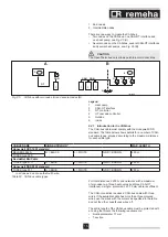
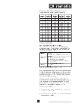
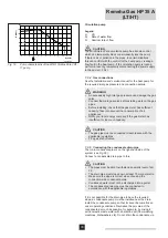
A. If the Gas HP heat pump is an end node in the network
(three wires connected to the orange connector on the
control unit), set the jumper as illustrated in
Fig. 07.
B. If the Gas HP heat pump is an intermediate node in the
network (six wires connected to the orange connector on
the control unit), set the jumper as illustrated for devices 1
and 2 in Fig. 08
.
6.4.3 Connecting the CAN-bus to the CAN-OT interface -
two nodes
Legend
GND Common data
L
LOW data signal
H
HIGH data signal
0 Zero
S SHIELD
(protection)
The CAN-bus cable is connected to the special yellow/green
HL0S
FRQQHFWRUWKDWLV¿WWHGLQWKH;FRQQHFWRURIWKH&$1
OT interface.
m
WARNING
Make sure the heat pump has been disconnected from the
power supply before starting work on the electrical panel.
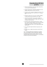
1. Open the CAN-OT interface from above by pressing the top
of the cover and carefully pulling it forward.
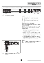
2. The jumpers on the CAN-OT interface must be set as
indicated in
Fig. 07
. The CAN/OT interface is an end node.
3. Cut off a piece of cable that is long enough for the
connection without any loops forming.
4. Remove approximately 20 mm of the cable casing and
the wires within it. Make sure you do not cut into the cable
protection (plaited metal or aluminium foil and, if present,
the bare connection in contact with the plait).
5. Disconnect the cable connector from connection
HL0S
on
connector
X2
.
6. Connect the cable's shield to connection
S
on connector
X2
.
7. Connect the cable to connector
X2
as indicated in
Fig. 07.
Pay attention to the marks on the connector where
GND
needs to be connected to
O
.
8. Refasten the cable connector on
X2
.
T003993-B
OT
On/off
OT
H
CAN
CAN / OT
S61
P8
X2
X1
H
L
L
0
0
S
S
Mains
N
N
L
L
GND L
H
Jumper
CN3
Jumper J1
(A)
Fig. 07
Connections on the CAN-OpenTherm interface and
Gas HP printed circuit board (two nodes)


