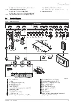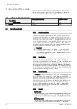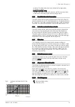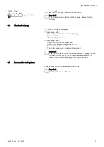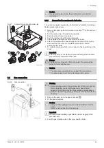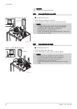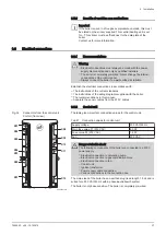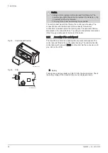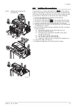
Tab.15 Type of flue gas connection: C
53
Principle
Description
AD-3001058-02
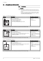
Connection in different pressure zones
Closed unit.
Separate air supply duct.
Separate flue gas discharge duct.
Discharging into various pressure areas.
The air supply and the flue gas outlet must not be placed on
opposite walls.
Connection material and roof
terminal:
Muelink & Grol
(1) The material must also satisfy the material property requirements from the relevant chapter.
Tab.16 Type of flue gas connection: C
63
Principle
Description
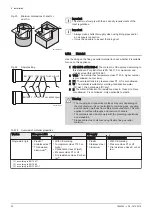
This type of unit is supplied by the manufacturer without an air
supply system and flue gas system.
When selecting the material,
please note the following:
Condensed water must flow
back to the boiler.
The material must be resist
ant to the flue gas tempera
ture of this boiler.
Maximum permissible recir
culation of 10%.
The air supply and the flue
gas outlet must not be placed
on opposite walls.
Minimum permitted pressure
difference between the air
supply and the flue gas outlet
is -200 Pa (including -100 Pa
wind pressure).
(1) The material must also satisfy the material property requirements from the relevant chapter.
Tab.17 Type of flue gas connection: C
93
Description
AD-3001059-01
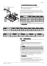
Room-sealed version
Air supply and flue gas discharge duct in shaft or ducted:
Concentric.
Air supply from existing duct.
Flue gas discharge via the roof.
Inlet opening for the air supply is in the same pressure zone
as the discharge.
Connection material and roof
terminal:
Muelink & Grol
(1) See table for shaft or duct requirements.
(2) The material must also satisfy the material property requirements from the relevant chapter.
Tab.18 Minimum dimensions of shaft or duct C
93
Version (D)
Without air supply
With air supply
Rigid 150 mm
Ø 200 mm
□ 200 x 200 mm
Ø 220 mm
□ 220 x 220 mm
Rigid 200 mm
Ø 250 mm
□ 250 x 250 mm
Ø 280 mm
□ 280 x 280 mm
Concentric 150/200 mm
Ø 270 mm
□ 270 x 270 mm
-
-
6 Installation
7665063 - v.05 - 18102018
31

