46
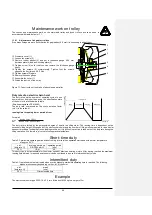
25. Loosen the screws (14) approximately a half turn (After about two adjustment procedures these
screws have to be replaced)
26. Tighten the hollow screws (5) approximately 1 mm towards the magnetic coil (1)
27. Tighten the screws (14) as much as an air gap of 0,4 mm between anchor plate (2) and magnetic
coil (1) is reached (use a thickness gauge to check)
28. Turn the hollow screws (5) out of the magnetic coil until they press against the basic plate (6) again
29. Tighten the screws (14) again equally
30. Double check the air gap again by using a thickness gauge
Make sure that the air gap has the same size all around the brake
31. If necessary readjust the air gap again
32. Use a torque wrench to tighten the screws (14) with 10 Nm
33. Refit the O- ring (15) and the dust protection ring (16) to the groove between magnetic coil and
brake disc
34. Connect the cable with the plug
35. Mount the fan cap
36. Connect mains supply again
37. Check for proper operation
If stopping the lowering movement with nominal load there should be a slide of not more than two chain
links. The load should not stop immediately to avoid any impact stress.
1.1.35
Electric control of brake
Mode of functioning
The disk brake is supplied through a rectifier circuit. It operates according to the fail safe principle. If there is a power
failure, the brake acts automatically so that the load is held securely in every position. To shorten the braking distance
the brake is operated in a D.C. circuit.
Sliding clutch
The sliding clutch is located between the motor and the brake so that the power from the brake to the
load is transmitted by gear parts in form-fitting connection. Even if the clutch is seriously worn, the load
will not fall uncontrolled as the load can be held in every position by the brake. The sliding clutch
operates as a dry clutch. The difference between the static and the sliding friction coefficients of the
asbestos-free lining is so slight that it has no effect on the functional reliability.
The sliding clutch is an
emergency stop
and it is not allowed to use it permanently.
Therefore the hoist is equipped with limit switches for lifting and lowering as standard.
1.1.36
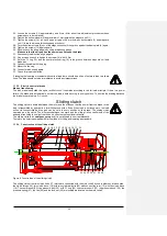
Construction of the sliding clutch
Figure 9: Construction of the sliding clutch
The sliding clutch from two clutch hubs (17) which are connected with the motor shaft by one feather key at each side,
the clutch linings (18), two clutch discs (19) with two cylindrical bolts (20) with connect the rotor (12) with the clutch discs
(19). The compressor (23), the pressure bolt (24) with O- ring (25), the compressor 2 (23), the pressure bush (26), the
pressure spring (27), the fan (28) and the lock nut (29) are located are located on the motor shaft.
17 18 19 20 21 10 20 19 18 17 22
24 25 23 26 27 28 29


