38
Replacement of the load chain
38. Hang the connecting piece, include in the delivery, into the inserted chain on the chain box side and
then attach the load chain to be drawn in.
39. Allow the load chain running in the by pressing the down button.
40.
Remove the connecting piece and the short piece of chain.
41. Attach the single fall hook to the load chain.
42. Lower the load hook to the lowest position.
43. Attach the end stop to the third chain link.
44. Mount the chain of the dead end according to 3.1.5.
45. Let the dead end of chain run into the chain box by pressing the up button and using the hoist
motor to prevent knots inside the chain box.
Caution!
If the chain has been completely removed from the hoist from any reason and short piece of
chain has inserted the clutch setting has be downrated to a minimum before a new chain can
be inserted. Please take care of this advice to prevent serious damages of the hoist if the first
chain link doesn't meet the pocket of the sprocket wheel.
D o u b l e f a l l o p e r a t i o n
Removing the worn load chain
1.
Remove the chain box (see section 3.1.5)
2.
Remove the two screws M6x20 DIN 912 and the axle suspension; remove the chain suspension
and second chain fall from the pocket, remove the double fall hook
3.
Remove the end stop by removing its two screws M12x60 DIN 912
4.
Hang the connecting piece and the short piece of chain into the worn load chain and insert them by
pressing a button.
5.
Remove the worn load chain from the connecting piece
Replacement of chain guide and hold down
6.
Remove the cover of the contactor control (four screws M6x75 DIN 912)
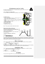
46. Dismantle the shaft of the limit switches as follows:
Remove the two tension pins 5x30
Remove the snap ring and the torsion spring
Remove the shaft of the limit switches
7.
Remove the two screws M16x120 DIN 912 of the chain guide in the control compartment of the
hoist.
8.
Remove the chain guide. (underside of casing)
9.
Remove the hold down (press it out with a screw driver
10. Insert the new hold down and the new chain guide
The pick up of the two screws M16x120 DIN 912 should not be more than 60 Nm
– insert the screws with new gasket rings
11. Insert the shaft for the limit switches (see remarks 3.2.2)
12. Assemble the cover of the contactor control compartment.
Replacement of the load chain
13. Hang the connecting piece, include in the delivery, into the inserted chain on the chain box side
and then attach the load chain to be drawn in.
14. Allow the load chain running in the by pressing the down button.
15.
Remove the connecting piece and the short piece of chain.
16. Attach the double fall hook to the load chain.
Caution!
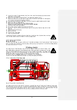
Never allow the chain to be twisted between the chain outlet and the hook block!
If the assembly according with figure 12 is not possible one chain link has to be cut
and removed to allow correct assembly.
20. Pull the chain out of the hook block and attach the first link horizontally into the double fall
suspension pocket.
21. Lock the chain with the suspension bracket and secure it with the bolt.
22. Check again that the chain is not twisted.
23. Secure the axle suspension with the cylindrical screws.
24. Lower the load hook to the lowest position.
25. Attach the end stop to the third chain link.
47. Mount the chain of the dead end according to 3.1.5.
26. Let the dead end of chain run into the chain box by pressing the up button and using the hoist
motor to prevent knots inside the chain box.
Caution!
If the chain has been completely removed from the hoist from any reason and short piece of
chain has inserted the clutch setting has be downrated to a minimum before a new chain can
be inserted. Please take care of this advice to prevent serious damages of the hoist if the first
chain link doesn't meet the pocket of the sprocket wheel.


