Reliable Controls SS-CO2-H-UD User Manual Download Page 74

65

The SS Worksheet

              U

SER

 G

UIDE

            SOFTWARE PROGRAMMING

SMART-S

ENSOR


2004 – 2014 Reliable Controls

®

 Corporation. All rights reserved.
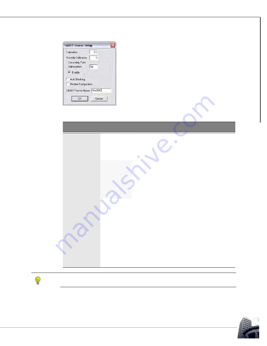
F

IGURE

 62: SMART-S

ENSOR


SETUP


DIALOG


BOX

T

ABLE

 14: SMART-S

ENSOR

 S

ETUP

 D

IALOG

 B

OX

Field

Description

Calibration

Used to calibrate the onboard temperature sensor ± 3.1 degrees
in °C or °F.

Humidity 
Calibration

Used to calibrate the onboard humidity sensor ± 31 percent in
%RH (-H models only).

Secondary 
Point

Abbreviation

Two character abbreviated name to be displayed
preceding the value of the secondary-point in 

Idle

mode.

Enable

Enables the display of the secondary point on the
top row of the LCD in 

Idle 

mode rather than the Tag

for Point 1.

Auto Blanking

The LCD reverts to the idle screen after 20 seconds of button 
inactivity. When Auto Blanking is enabled, the LCD automatically 
turns off after 20 seconds of button inactivity in the idle screen (40 
seconds of inactivity before screen blanking occurs). The display 
will reappear in 

Idle 

mode when any button is pressed.

Disable 
Configuration

Locks out the configuration abilities of the SS-L inherent in the
firmware. If this box is enabled, the SS-L may not be used as a
SETUP-Tool

 or Flow Tool.

SMART-Sensor 
Name

Twenty character name for the SMART-Sensor

 LCD that will

appear in the 

SMART-Sensor 

worksheet title bar and the System

Tree.

If 

Time

 is selected as the Range for the secondary point, the abbreviation will not be shown.

Instead, AM or PM will be displayed.

Summary of Contents for SS-CO2-H-UD

Page 1: ...SMART Sensor better by design User Guide...

Page 2: ......

Page 3: ...User Guide better by design SMART Sensor 2002 2014 Reliable Controls Corporation All rights reserved...

Page 4: ...s pan Click the Save button Italics in lowercase for field values file types directories and file paths e g The value of the Panel Program field is pan The pan files are stored in the pan subdirectory...

Page 5: ...on of Reliable Controls Corporation www reliablecontrols com Reliable Controls RC Studio and the Reliable Controls logo are registered trademarks of Reliable Controls Corporation BACnet is a registere...

Page 6: ...SS DUCT GD MODELS 13 MODELS 14 BASE MODELS 14 ORDERING OPTIONS 18 SMART NET NETWORK TOPOLOGY 22 SENSORS PER CONTROLLER 22 MAXIMUM CABLE LENGTHS 23 SMART SENSOR EXPANSION BOARD SSX 24 SSX PORTS 25 POWE...

Page 7: ...POINT 54 QUICK ADJUST MODE 55 DISPLAY POINT MODE 55 BACKLIGHT FOR THE SS L 56 SOFTWARE PROGRAMMING 57 ACCESSING THE SS WORKSHEET 57 THE SS WORKSHEET 60 VALUES DISPLAYED 60 RESERVED POINTS 61 COLUMNS 6...

Page 8: ...OWER 112 DISPLAY SS L ONLY 112 NETWORK 112 COMMISSIONING PROGRAMMING 112 AMBIENT LIMITS 113 PHYSICAL 113 ONBOARD TEMPERATURE SENSOR 114 ONBOARD HUMIDITY SENSOR OPTIONAL 114 SS MODELS WITH H OPTION 114...

Page 9: ...vi 2004 2014 Reliable Controls Corporation All rights reserved NOTES...

Page 10: ...W SS P SS DUCT PB AND SS DUCT GD SS FEATURES INCLUDE Network up to 16 SMART Sensors on a single SMART Net network depending on the host controller type Fully compatible with all generations of MACH Sy...

Page 11: ...2 2004 2014 Reliable Controls Corporation All rights reserved SS P Measure room temperature in locations where the sensor could be subject to damage SS DUCT Measure duct temperature and humidity...

Page 12: ...ion All rights reserved GETTING STARTED PACKAGE CONTENTS SMART SENSOR PACKAGE CONTENTS One SMART Sensor with backplate SS SS L or SS coverplate SS P or wiring box SS DUCT SS SS L Two 6 32 1 Phillips s...

Page 13: ...2 PHYSICAL LAYOUT SS L OC SS L D PICTURED Backplate Sensor head LCD screen optional Optional occupancy sensor Three button keypad X Port 2 access port Two 1 6 mm 1 16 Allen screws secure sensor head t...

Page 14: ...rols Corporation All rights reserved SS MODELS FIGURE 3 PHYSICAL LAYOUT SS CO2 UD AND SS S PICTURED Optional Setpoint Buttons SS CO2 UD Optional Slider SS S Thicker backplate for CO2 models Two 1 6 mm...

Page 15: ...6 2004 2014 Reliable Controls Corporation All rights reserved SS P MODELS FIGURE 4 PHYSICAL LAYOUT SS P AND SS P O PICTURED SS Plate SS P SS Plate with Override SS P O...

Page 16: ...cal Layout USER GUIDE GETTING STARTED SMART SENSOR 2004 2014 Reliable Controls Corporation All rights reserved SS DUCT MODELS FIGURE 5 PHYSICAL LAYOUT SS DUCT PB AND SS DUCT GD PICTURED SS DUCT PB SS...

Page 17: ...8 2004 2014 Reliable Controls Corporation All rights reserved PHYSICAL DIMENSIONS SS AND SS L MODELS FIGURE 6 PHYSICAL DIMENSIONS SS L PICTURED 12 cm 4 3 4 2 4 cm 15 16 7 cm 2 3 4...

Page 18: ...04 2014 Reliable Controls Corporation All rights reserved FIGURE 7 STANDARD BACKPLATE PHYSICAL DIMENSIONS USED FOR ALL SS SS L MODELS EXCEPT CO2 3 5 cm 1 3 8 1 3 cm 1 2 3 0 cm 1 3 16 3 0 cm 1 3 16 8 2...

Page 19: ...poration All rights reserved FIGURE 8 BACKPLATE PHYSICAL DIMENSIONS USED FOR SS SS L MODELS WITH CO2 OPTION 7 1 cm 2 13 16 1 2 wire grommet fits two CAT5 cables 12 1 cm 4 3 4 0 9 cm 3 8 0 9 cm 3 8 1 9...

Page 20: ...Corporation All rights reserved SS P MODELS FIGURE 9 PHYSICAL DIMENSIONS SS P PICTURED The SS P circuit board will fit into a back box or wall opening sized 3 73 x 6 85 cm 1 1 2 x 2 3 4 or greater 6 9...

Page 21: ...ntrols Corporation All rights reserved SS DUCT PB MODELS FIGURE 10 PHYSICAL DIMENSIONS SS DUCT 4 PB PICTURED 10 2 cm 4 12 2 cm 4 3 4 6 0 cm 2 3 8 5 7 cm 2 1 4 9 1 cm 3 5 8 7 6 cm 3 10 2 15 2 20 3 30 5...

Page 22: ...11 PHYSICAL DIMENSIONS SS DUCT 4 GD PICTURED FIGURE 12 PHYSICAL DIMENSIONS SS DUCT EH RH PICTURED 10 7 cm 4 3 16 5 0 cm 2 5 9 cm 2 5 16 9 8 cm 3 7 8 7 8 cm 3 13 16 10 2 15 2 20 3 30 5 45 7 cm 4 6 8 12...

Page 23: ...MODELS BASE MODELS SMART SENSOR FIGURE 13 SS BASE MODEL One onboard space temperature sensor 10k thermistor 40 C to 40 C 40 F to 104 F One RJ11 connector on bottom to provide network access X Port 2 c...

Page 24: ...ved SMART SENSOR LCD FIGURE 14 SMART SENSOR LCD One onboard space temperature sensor 10k thermistor 0 C 32 F to 40 C 104 F One RJ11 connector on bottom to provide network access X Port 2 converter req...

Page 25: ...ntrols Corporation All rights reserved SMART SENSOR PLATE SS P FIGURE 15 SMART SENSOR PLATE SS P ACI Stainless Plate temperature sensor 10k thermistor 0 C 32 F to 50 C 122 F Foam pad insulating sensor...

Page 26: ...RT SENSOR DUCT FIGURE 16 SMART SENSOR DUCT SS DUCT 4 PB AND SS DUCT 4 GD SS DUCT PB ACI Plastic Box Duct temperature sensor 10k thermistor 40 C 40 F to 85 C 185 F SS DUCT GD ACI Galvanized Metal Duct...

Page 27: ...ng and humidity sensor to DUCT models H Adds humidity sensor to SS and SS L models IO Adds 2 inputs and 2 TRIAC outputs not available on P models L Adds LCD to base model O Adds override button not av...

Page 28: ...with LED back light 2 humidity sensor 2 dry contact Inputs and 2 TRIAC Outputs SS L BL IO LCD with LED back light 2 dry contact Inputs and 2 TRIAC Outputs SS L BL OC LCD with LED back light PIR Motion...

Page 29: ...or SS P O Stainless wall plate temp sensor and override button SS DUCT 4 PB Plastic box duct mount temp sensor with 4 probe length SS DUCT 4 GD Galvanized metal duct mount temp sensor with 4 probe len...

Page 30: ...metal duct mount temp sensor with 18 probe length 2 dry contact inputs and 2 SSR outputs SS DUCT EH RH2 Euro housing combination sensor 7 25 inch probe for duct temperature and 2 humidity sensor SS DU...

Page 31: ...or the terminal blocks provided Any mix of SS models may be installed on a single daisy chain SMART Sensor Enocean Access Points SSEAs can also be added to the mix however each SSEA uses up two addres...

Page 32: ...g formulas can be used to calculate the maximum length of selected cable Rmax Vmax D Rmax Imax Rc Where D distance in meters Rmax maximum total cable resistance Rc resistance per meter of cable Vmax m...

Page 33: ...lly each SSX can be connected to an external power source for the purpose of boosting the power to connected SSs allowing the combined overall cable length of a SMART Net to be maximized FIGURE 17 SMA...

Page 34: ...gth SS models with I O backlight or CO2 require more current An SSX is recommended for applications where more than four SSs are installed on the same SMART Net network or where the total combined cab...

Page 35: ...IA 485 network is extended and the SSX is the physical extremity of the network the End of Line EOL termination jumpers JP2 JP3 of the SSX should be installed and the EOL jumpers switches on the host...

Page 36: ...he default factory settings by leaving the jumpers out This will improve EIA 485 network performance It will have no effect on SMART Net performance However the ability to connect an X Port 2 converte...

Page 37: ...3 Connect the first SS to any of the PROG SENS ports on the SSX using a rollover SS VC 4 Connect the second and subsequent SSs to the first SS using straight through Data Cables SS DC between each SS...

Page 38: ...e Controls Corporation All rights reserved The following diagram shows the optimal configuration for one SSX connected to a MACH ProSys controller with the maximum of 16 connected SSs FIGURE 22 FULLY...

Page 39: ...e to daisy chain subsequent SSX expansion boards in this manner as required 4 Connect the first SS to any free PROG SENS port on any SSX using a rollover SS VC 5 Connect the second and subsequent SSs...

Page 40: ...rved The following diagram shows the optimal configuration for two SSX expansion boards connected to a MACH ProSys controller with the maximum of 16 connect SSs FIGURE 23 FULLY LOADED SMART NET WITH 1...

Page 41: ...uired FIGURE 24 1 16 FLEXIBLE ALLEN KEY PM ALLENKEY A flat blade instrument screwdriver with 3 mm 1 8 wide blade for wire terminal screws and A 1 16 Allen key for the Allen screws that secure the SS h...

Page 42: ...et communication wiring 24 26 AWG 0 25 0 14 mm2 solid or 26 28 AWG 0 14 0 08 mm2 stranded 6 conductor cable is recommended 2 If connection to the RJ11 SMART Net port at the host controller is required...

Page 43: ...the two Allen screws at the bottom of the controller This is counterintuitive but works by moving the Allen screws inward and out of the way of the sensor head FIGURE 26 ALLEN KEY 2 Pull the bottom o...

Page 44: ...35 SS and SS L Models USER GUIDE INSTALLATION SMART SENSOR 2004 2014 Reliable Controls Corporation All rights reserved 3 Separate the backplate from the SS sensor head FIGURE 28 BACKPLATE SEPARATION...

Page 45: ...hod is preferred as it provides a firm mounting base for the sensor FIGURE 29 ELECTRICAL BOX MOUNTING Use the two Phillips screws provided to attach the backplate to the underlying electrical box or m...

Page 46: ...uctors to the SMART Sensor using either the 6 pole terminal strip on the backplate or by crimping an RJ11 connector and plugging it into either of the onboard RJ11 sockets on the back of the SS FIGURE...

Page 47: ...t the included one inch 8 sheet metal screws 2 through the mounting holes in the flange and tighten them until the unit is held firmly to the duct FIGURE 32 MOUNTING AN SS DUCT TO TERMINATE THE CABLIN...

Page 48: ...ny drafts in the wall There are two machine screws 6 32 x 1 provided for junction box mounting 2 Insert 2 screws through the mounting holes and tighten them until the unit is held firmly in place Ensu...

Page 49: ...ost controller Do not mount the SS above or on the surface of heat producing sources below cooling sources near windows behind obstructions or in areas prone to infiltration When mounted in or on holl...

Page 50: ...id core conductors are recommended SS P SS DUCT and SSEAs do not have RJ11 ports and must be terminated using the four wire connectors provided Four conductors are required to support SMART Net If the...

Page 51: ...TROLLER TO FIRST SS FIGURE 38 RJ11 PIN OUT BETWEEN CONTROLLER AND FIRST SS USING A ROLLOVER CABLE If a controller s SMART Net terminal block is used the wiring connections should match point to point...

Page 52: ...addition to the standard RJ11 connector Either of these methods can be used for SMART Net wiring Note that the terminal block does not include terminals for the A and B EIA 485 conductors If the EIA...

Page 53: ...g a daisy chain topology Either the terminal block or RJ11 socket may be used to terminate the SMART Net at each SS FIGURE 41 CABLING FROM SS TO ADDITIONAL SSS FIGURE 42 RJ11 PIN OUT BETWEEN TWO SSS T...

Page 54: ...SER GUIDE INSTALLATION SMART SENSOR 2004 2014 Reliable Controls Corporation All rights reserved FIGURE 43 CONNECTING TO MULTIPLE SS LS MACH ProSys Voice Cable SS VC rollover cable Data Cable SS DC str...

Page 55: ...in Figure 44 FIGURE 44 PROTECTOR DIRECTOR FOR THE SS SS P AND THE SS DUCT SHOWING THE ADDRESS CONFIGURATION The 16 possible addresses are represented in binary and switch 4 the switch located a the t...

Page 56: ...of the SS L The default SS L address is 1 FIGURE 45 SS L ADDRESS SCREEN 4 Press the or to configure the desired SS L address between 1 and 16 5 After the desired configuration is complete allow the o...

Page 57: ...CHANGE THE SECONDARY DISPLAY POINT 1 The secondary point display may also be configured using the SS L Addressing feature 2 After the initialization sequence hold the and buttons for five seconds rele...

Page 58: ...t the value of the Quick adjust point typically a setpoint TEST LED SS models without the LCD screen have a Test LED located at the bottom of the circuit board next to the onboard temperature sensor T...

Page 59: ...d When the middle button on a model with an override button is pressed and point 3 is set to digital ON OFF the digital value is set TRUE or ON and a 10 minute timer is initialized After 10 minutes ha...

Page 60: ...han its SMART Net host however those points cannot be adjusted by an operator using the SS L buttons If the SMART Net host is a BACnet only device e g MACH ProZone MACH ProAir then any network points...

Page 61: ...g points or toggle the status of binary points configured to permit operator modification Pressing the decrement button will decrease the value of analog points or toggle the status of binary points c...

Page 62: ...g to the right selects degrees F The Degree C F switch only invokes a local conversion on the SS L D It does not affect RC Studio System Groups or Control BASIC functionality in any way FIGURE 52 SS L...

Page 63: ...e of the point or object configured in row number one of the SS L worksheet in the center or middle row of the LCD Any points or objects configured to appear as an icon will be displayed in the bottom...

Page 64: ...d Pressing the or button further will decrease or increase the point value typically a setpoint After the desired adjustment is complete the display will continue to flash briefly until the value is c...

Page 65: ...he backlight turns on whenever any of the buttons are pressed and remains on for 10 seconds after last button press The present value or state of any point or object that is configured for Can Change...

Page 66: ...the SMART Net host is a BACnet only device e g MACH ProZone MACH ProAir then any network points to be displayed must be entered using BACnet references If the SMART Net host supports Reliable Controls...

Page 67: ...or any controller in the System Tree by clicking the next to the SMART Sensors node A list of available SMART Sensor worksheets is displayed There is a separate worksheet for each possible SS SMART Ne...

Page 68: ...IGURE 60 SMART SENSOR 1 WORKSHEET 3 To configure the display of a specific SMART Sensor LCD use the SMART Sensor worksheet To open the worksheet click the desired sensor from the SMART Sensors node in...

Page 69: ...yed If the point or object in row two is set to Can Change in the User Edit column when the value is accessed as the quick adjust point the value will be displayed flashing steadily and may be modifie...

Page 70: ...for O models only when the range is set to On Off Point 4 Onboard humidity sensor for H models and SS DUCT EH RH only Point 5 Onboard motion sensor for OC models only Point 6 Onboard CO2 sensor for C...

Page 71: ...e chosen allowing selection of an appropriate display range for the value State Off On Low High Cool Heat Off Low High Off On Auto Fan Off Low Medium High Off Auto Manual Cool Heat Auto Off Analog 0 D...

Page 72: ...name that will be displayed on the LCD screen together with the present value when the operator scrolls to the point If this column field is left empty the row number will be displayed Typing the val...

Page 73: ...y field may be selected for modification If the icon is displayed the vale in the field selected may be edited In this mode data is not dynamically updated When the mode is toggled from mode or mode t...

Page 74: ...Idle mode rather than the Tag for Point 1 Auto Blanking The LCD reverts to the idle screen after 20 seconds of button inactivity When Auto Blanking is enabled the LCD automatically turns off after 20...

Page 75: ...SS IO inputs may be used to connect either dry contacts or 10 k thermistors The field devices wire directly to the input terminal block on the SS IO A variable VAR must be created in the host controll...

Page 76: ...d in the host controller to store a value corresponding to each output The variables that represent the outputs are then referenced using row 9 and row 10 of the SMART Sensor worksheet To permit an op...

Page 77: ...4VAC DC 0 5A SS IO outputs terminate consistent with all MACH series TRIAC outputs as detailed in Figure 65 FIGURE 65 SS IO AND SS DUCT OUTPUT WIRING TABLE 16 SS IO OUTPUT PROGRAMMING DETAIL Physical...

Page 78: ...ET RESERVED POINTS Reserved points for inputs and onboard sensors must be set to Can Change so that the SS can write to variables in the host controller Output points do not need to be set to Can Chan...

Page 79: ...some significant differences from non CO2 models including FIGURE 67 SS CO2 MODEL CIRCUIT BOARD The duplex RJ11 connection port on the rear of the sensor head has been removed to make room for the CO...

Page 80: ...grommet in the center of the backplate for wire penetration This small opening will minimize unwanted drafts that may exude from a wall especially when no insulation is present The mounting holes hav...

Page 81: ...ns where the CO2 sensor is exposed to fresh air CO2 concentrations of 400 ppm at least once per week the automatic calibration routine will calibrate the sensor to specification within about 3 weeks F...

Page 82: ...alue recorded actually was 600 PPM the sensor would be out of calibration by 200 ppm following execution of the automatic calibration algorithm For applications such as continuously occupied rooms or...

Page 83: ...example shown in Figure 70 the reference sensor measured 450 PPM therefore CAL450 was entered in the Tag field FIGURE 70 SMART SENSOR WORKSHEET MANUAL CALIBRATION USING THE TAG FIELD 3 Activate the M...

Page 84: ...re some important facts regarding configuration that should be remembered to ensure the proper functionality of the SS CO2 such as Set the Type column value in the SMART Sensor worksheet to Analog Set...

Page 85: ...s reset to the default Whenever the occupancy sensor transitions to the False state the ton timer starts timing down The occupancy sensor state may change many times but the SS occupancy state will re...

Page 86: ...l rights reserved Figure 72 illustrates the viewing angles within which the occupancy sensor can detect motion FIGURE 72 MOTION DETECTION ANGLES 0 50 50 0 41 41 5 m 16 ft 5 in 2 5 m 8 ft 2 in 2 5 m 8...

Page 87: ...t model to choose will be the model with the tip of the probe as close to the centerline of the duct as possible The simplest way to calculate the probe length needed is by taking the depth of the duc...

Page 88: ...ct the A and B pins of the SMART Net network to the controller s EIA 485 communication network effectively extending the local controller network to the SS RJ11 access port An X Port 2 plugged into an...

Page 89: ...r to the serial port adapter of the workstation CC C1 C cables CC C1 B RJ 11 to 9 pin adaptor and CNV USB 232 as detailed below are standard part numbers available from Reliable Controls FIGURE 75 X P...

Page 90: ...he three button keypad interface of the SS L Table 17 details the key code combination necessary to access each configuration tool TABLE 17 SS L ONBOARD CONFIGURATION TOOL KEY CODE COMBINATIONS Point...

Page 91: ...SMART Net address of the SS L and the secondary point TO USE THE SS L ADDRESS TOOL 1 Access the SS L Address Tool using the appropriate key code combination outlined in Table 17 2 SSLADDR will display...

Page 92: ...ters to be configured in order to successfully communicate to other controllers on an EIA 485 network This configuration may be performed using the SS L onboard Setup Tool rather than using the RC Too...

Page 93: ...ress BAUD 9600 192 384 768 9600 EIA 485 network baud 9 6 kbps 192 EIA 485 network baud 19 2 kbps 384 EIA 485 network baud 38 4 kbps 768 EIA 485 network baud 76 8 kbps SUBNET No Yes No home network mai...

Page 94: ...of or Last The value should display a if the controller is not the highest physical address on an RCP or BACnet network The value should display a Last if the controller is the highest physical addre...

Page 95: ...no utilize Last Panel to facilitate the token passing scheme implemented for communication For this reason on BACnet networks it is recommended that Last Panel not be used Therefore no controllers wo...

Page 96: ...e Flow Tool VARs are outlined in Figure 76 and Table 19 FIGURE 76 SS L FLOW TOOL WORKSHEET IN THE STANDARD PAN FILE IN ALL MACH AIR CONTROLLERS The SSL onboard Flow Tool requires a pre configured SS L...

Page 97: ...low calibration of a MACH Air or MACH ProAir controller set the minimum VAVx FLO MIN and maximum airflow setpoints VAVx FLO MAX OCC the VAV box inlet duct diameter VAVx DIAM IN and the damper actuator...

Page 98: ...ton to step to the FLOW point on the SS L and wait until the displayed calculated flow stabilizes depending upon system conditions and flow sensor calibration the displayed flow may not reach the FL O...

Page 99: ...e of the specified or acceptable limits 5 10 typical repeat steps 5 8 10 If it is necessary to balance or test the VAV box at the configured minimum airflow setpoint repeat steps 2 4 using the minimum...

Page 100: ...plete to allow the MACH Air to revert to normal programmed operation This VAR overrides the control airflow setpoint and any value 0 will prevent the MACH Air from controlling as programmed 1 Connect...

Page 101: ...default SMART Net address of 1 TO CHANGE THE ADDRESS 1 Locate the DIP switch rack and configure the address by closing or opening the appropriate switches as shown below 2 The 16 possible addresses a...

Page 102: ...Corporation All rights reserved TO CONFIGURE THE SS 1 After the hardware configuration of the SS is complete Use RC Studio 2 0 to configure the SS Using RC Studio 2 0 connected to the desired system f...

Page 103: ...ype Locate the desired Sensor node and click it to open the corresponding worksheet In 61 Sensor 1 is selected to configure the SS at address number 1 FIGURE 85 SELECT AN SMART SENSOR WORKSHEET SENSOR...

Page 104: ...etpoint must be entered in Row 2 On O models the VAR used to map the override button must be entered in Row 3 with a Range set to On Off On H models the VAR used to map relative humidity must be enter...

Page 105: ...5 Rm1 Motion State 1VAR5 Can Change Point 6 Rm1 CO2 Analog 1VAR6 Can Change All values that must be modifiable by the SS including both onboard options and or operator modification will have to be co...

Page 106: ...ced from the Variable worksheet from a single network controller FIGURE 88 SS PROGRAMMING EXAMPLE HOST POINT VARIABLES WORKSHEET FIGURE 89 SS PROGRAMMING EXAMPLE SMART SENSOR WORKSHEET WITH POINT REFE...

Page 107: ...ator interface buttons or slider and 2 input sensors If the User Edit column is set to a value of Display Only then the SS cannot change the value of a point 7 After the SS display programming is comp...

Page 108: ...ary point on the top row in Idle mode If the secondary point is enabled a two character descriptive abbreviation may be programmed to be displayed together with the value Disable the onboard configura...

Page 109: ...een installed according to the installation guidelines in this manual When initially connected to the SMART Net or powered up the SS L displays all LCD segments for two seconds followed by the SS L ad...

Page 110: ...All rights reserved TO CONFIGURE THE SS L 1 After the hardware configuration of the SS L is complete Use RC Studio 2 0 to configure the LCD display of the SS L Using RC Studio 2 0 connected to the de...

Page 111: ...Locate the desired Sensor node and click it to open the corresponding worksheet In Figure 94 Sensor 1 is selected to configure the SS L at address number 1 FIGURE 94 SELECT A SMART SENSOR WORKSHEET S...

Page 112: ...nsor worksheet and select the suitable temperature range On H models the VAR used to map relative humidity must be entered in Row 4 On OC models the VAR used to map the motion sensor must be entered i...

Page 113: ...e for a technician to use for quick troubleshooting How should the points be displayed Is an icon preferable and perhaps more descriptive for some points than showing a value Which points will need to...

Page 114: ...10 AH01 SF S State 1IN4 Display Only All values that must be modifiable by the SS L including both onboard options and or operator modification will have to be configured to Can Change 6 Program each...

Page 115: ...rom two different controllers FIGURE 97 SS L PROGRAMMING EXAMPLE HOST POINT WORKSHEETS INS OUTS VARS FIGURE 98 SS L PROGRAMMING EXAMPLE SMART SENSOR WORKSHEET WITH POINT REFERENCES Remember that the p...

Page 116: ...the value of an analog point is to be displayed the appropriate engineering unit can be selected from the available units by pressing the spacebar or clicking the desired Unit Icon cell Binary or Mul...

Page 117: ...ped point Also notice that an icon has been selected for AH01 SF S in Row 10 When the mapped point is true has a value of 1 the small fan icon will appear on the default screen When the mapped point i...

Page 118: ...mming to the host controller of the SS L 12 Verify proper operation of the SS L including Are all of the programmed points displaying on the SS L as configured In the mode do the Value columns of the...

Page 119: ...yed together with the value The LCD reverts to the idle screen after 20 seconds of button inactivity When Auto Blanking is enabled the LCD automatically turns off after 20 seconds of button inactivity...

Page 120: ...state an icon is selected and the User Edit field is set to Display Only the icon will be displayed according to the value of the point displayed in Idle mode but the point will not appear separately...

Page 121: ...A LCD 132 segment LCD 12 o clock viewing angle Viewable Area 36 mm x 36 mm 1 3 8 x 1 3 8 Network SMART Net Ports Two RJ11 SMART Net ports not available on CO2 DUCT and P models One 6 wire SMART Net te...

Page 122: ...D 3 25 cm for CO2 4 3 4 H x 2 3 4 W x 15 16 D SS DUCT GD 10 16 cm H x 5 41 cm W x 5 02 cm D 4 H x 2 1 8 W x 2 D SS DUCT PB 12 17 cm H x 5 72 cm W x 5 97 cm D 4 3 4 H x 2 1 4 W x 2 3 8 D SS DUCT EH RH...

Page 123: ...104 F SS P 0 C to 50 C 32 F to 122 F SS DUCT 40 C to 60 C 40 F to 140 F Resolution 0 1 C 0 18 F below 90 C 194 F 0 2 C 0 36 F above 90 C Accuracy 1 C 1 8 F below 90 C user calibrated to 0 1 C 1 5 C 2...

Page 124: ...ive Infrared Radiation PIR Detection Distance 5 m 16 ft maximum Detection Angle 100 horizontal 82 vertical Detection Zones 64 Type Non dispersive infrared optical sensor Range 0 2000 PPM Resolution 1...

Page 125: ...hts reserved AUXILIARY OUTPUTS OPTIONAL IO MODELS ONLY SS MODELS WITH IO OPTION SS DUCT MODELS WITH IO OPTION Quantity Two Type TRIAC Rating 20 500 mA current load 24 VAC Quantity Two Type Solid state...

Reviews: