8
OPERATING AND MAINTENANCE MANUAL
Chapter 3 - Technical data
TAE K15÷K20
The data in this manual are not binding and may be changed by the manufacturer without notice.
Reproduction of this manual, even partial, is strictly prohibited.
C
HAPTER
3
T
ECHNICAL
DATA
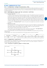
The main technical data are given on the machine data plate:
ATTENTION
The performance of the unit mainly depends on the flow and temperature of the water in the user circuit and on the temperature of the
thermal exchanger fluid of the condenser. These data are defined during the offer stage.
3 . 1
O t h e r d a t a r e l a t i v e t o t h e s t a n d a r d m a c h i n e s
3.1.1 Dimen sions
See enclosures.
3.1.2 Characteristics of p ump s
NOTE
The values in the table may vary in relation to the model and configuration of the unit. In this case reference should be made to the data in the
offer.
NOTE
The head is the head available to the user. It is possible for the pump installed to be different from the standard. There are two numbers for
the flow rate and pressure: the first number refers to the nominal conditions while the second to the maximum conditions.
MODEL and CODE
They identify the size of the unit and the type of construction.
MANUAL
This is the code number of the manual.
SERIAL NUMBER
This is the construction number of the unit.
MANUFACTURING YEAR
This is the year of the final test of the unit.
VOLTAGE/PHASE/FREQUENCY
Electric alimentation characteristics.
MAX. CONSUMPTION (I max)
This is electrical current consumed by the unit during the limit working conditions.
INSTALLED POWER (P max)
It is the power absorbed by the unit during the limit working conditions.
PROTECTION
As defined by the EN 60529 European standard .
REFRIGERANT
This is the refrigerant fluid in the unit.
REFRIGERANT QUANTITY
This is the quantity of refrigerant fluid contained in the unit.
MAX. COOLING PRESSURE
This is the design pressure of the refrigeration circuit.
MAX. COOLING TEMPERATURE
This is the design temperature of the refrigeration circuit.
USER CIRCUIT FLUID
Fluid used by the unit (normally water).
MAX. UTILIZATION PRESSURE
Max. designed pressure of the utilization circuit.
MAX. TEMPERATURE
Design temperature of the user circuit; this should not be confused with the maximum
working temperature which is established when the offer is made.
CONDENSER COOLING FLUID
Fluid the machine uses to cool the condenser.
MAX. WORKING PRESSURE
Maximum design pressure of the condenser cooling circuit.
MAX. TEMPERATURE
Maximum designed temperature of the cooling circuit of the condenser.
SOUND PRESSURE LEVEL
Sound pressure level in a free field in hemispherical irradiation conditions (open field)
at a distance of 1 m from the machine, condenser side, and at 1.6 m from the ground.
AMBIENT TEMPERATURE
Min. and max. cooling air temperature value.
WEIGHT
This is the approximate weight of the unit before packing.
Table 2
D
ATA
PLATE
AND
MEANING
OF
ABBREVIATIONS
Model
K15
K20
Tank capacity
water volume
(litres)
(galUS)
50
13
50
13
PUMP
water flow rate
(m
3
/h)
(gpm)
1.2/4.8
5.3/21.1
1.2/4.8
5.3/21.1
pump head
(bar)
(PSI)
5.2/2.4
75.4/34.8
5.2/2.4
75.4/34.8
nominal power
(kW)
1.65
1.65
Table 3
C
HARACTERISTICS
OF
STANDARD
UNITS


