17
OPERATING AND MAINTENANCE MANUAL
Chapter 7 - Electronic Board
TAE K15÷K20
The data in this manual are not binding and may be changed by the manufacturer without notice.
Reproduction of this manual, even partial, is strictly prohibited.
7.5.1 Alarm icons
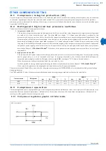
There are four icons for alarm signalling:
7 . 6
H o w t o s i l e n c e t h e b u z z e r
Automatic silencing:
it happens when the cause of the alarm has been eliminated.
Manual silencing:
press and release one of the four buttons; the buzzer silences even if the alarm condition persists.
7 . 7
F i r s t s t a r t u p
At the first start up of the unit in the bottom part of the display it could appear the message “
$%&
” alternated with the temperature. It indicates
that it is necessary to regulate the clock.
If the probes used to control the unit are not connected or are damaged, the appropriate alarm will be displayed.
However, it is possible to regulate the clock or to programme the unit.
7 . 8
P r o g r a m m i n g b y k e y b o a r d
The parameters of electronic control are divided in two groups and in two levels:
1.
USER (Pr1);
2.
SERVICE (Pr2).
USER level allows to access user parameters, SERVICE level allows to access the parameters of unit configuration (it is protected by a
password).
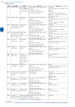
The parameter’s groups, indicated by some “Label”, are divided as follows:
7.8.1 Access to “Pr1” paramet ers (User level)
To enter the menu of “
Pr1
” parameters which can be access by the user:
1.
Press for some seconds
4
+
"
buttons (
7
and
#
start flashing), in the top of the display appears “
ALL
”, the first group of
parameters.
2.
Select the various groups using
>
and
"
buttons.
3.
After selecting a group, press
4
button: if the selected group is part of the selected menu or any parameter of this group has been
moved in this menu, in the bottom of the display it appears the “Label” and the code of the group’s first parameter present in “
Pr1
”,
its value appears in the top of the display.
It will not be possible to enter a parameter’s group which is not part of this menu.
4.
It is possible to scroll or modify the parameters contained in the group.
7.8.2 How to modify a p arameter’s valu e
1.
Enter the programming procedure.
2.
Select the desired parameter.
3.
Press
4
button to enable the value’s adjustment.
4.
Modify the value by means of
>
and
"
buttons.
5.
Press
4
to store the new value and to pass to the code of the following parameter.
6.
To exit the procedure: Press
4
+
>
when a parameter is displayed, or wait (about 240 seconds) without pressing any button.
/
General alarm
1
High pressure alarm
%
Low pressure alarm
*
Flow meter alarm
LABEL
ACTION
ALL
It displays all parameters
ST
It displays Thermoregulation parameters
CF
It displays Configuration parameters
Sd
It displays only the parameters of the Dynamic Setpoint (NOT ENABLED FUNCTION)
ES
It displays only the parameters of the Energy Saving (NOT ENABLED FUNCTION)
CO
It displays Compressor parameters
FA
It displays Fan parameters
Ar
It displays only the parameters of the Antifreeze Resistance
dF
It displays only the parameters of the Defrosting (NOT ENABLED FUNCTION)
AL
It displays only the Alarm parameters
LS
It displays only the LASER parameters (NOT ENABLED FUNCTION)


