22
Chapter 7
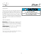
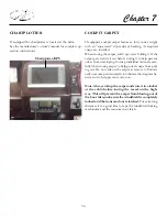
MONITOR PANEL
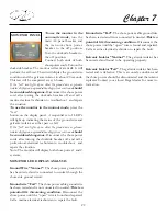
To use the monitor in the
automatic mode,
turn the
main AC panel breaker and
the transom shore power
breaker to the off position.
Turn the dockside breaker to
the off position.
Connect both ends of both
shore power cords. Turn on the
dockside breaker. The monitor will activate itself. It will
perform the self-test. Then it will display the ground wire
condition and the galvanic isolator in about 20 seconds.
This test will be completed every 6 hours.
If the “fail” icon lights up on either the ground wire or galvanic
isolator displays an ungrounded bonding system exists and
should
be considered dangerous.
Disconnect the shore power
cord after turning the dockside breaker off and call a
marine electrical technician to troubleshoot and repair
the situation.
To use the monitor in the manual mode,
press the
“test”
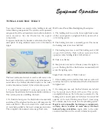
button on the display panel. A sequential set of LED’s
will light up indicating the status of the ground wire and
galvanic isolator as either pass or fail.
If the “fail” icon lights up on either the ground wire or galvanic
isolator displays an ungrounded bonding system exists and
should
be considered dangerous.
Disconnect the shore power
cords after turning the dockside breaker off and call a
professional electrical technician to troubleshoot and
repair the situation.
Note: The monitor will display both shore power 1 and 2
systems.
Ground Wire “Normal”
- The shore power ground wire
has been tested and is connected to neutral through the
shore side ground circuit.
Ground wire “Fail”
- The shore power cable ground wire
has been tested and is not connected to neutral.
This is a
potential life threatening condition.
Disconnect the
shore power until the “open” wire is found and repaired.
Call a marine electrical technician to repair the fault.
MONITOR LED DISPLAY ANALYSIS
Ground wire “Fail”
- The shore power cable ground wire
has been tested and is not connected to neutral.
This is a
potential life threatening condition.
Disconnect the
shore power until the “open” wire is found and repaired.
Call a marine electrical technician to repair the fault.
Galvanic Isolator “Normal”
- The galvanic isolator has
been tested and found to be operating properly.
Galvanic Isolator “Fail”
- The galvanic isolator has been
tested and is defective. This is an unsafe condition and
the shore power should be disconnected and the isolator
replaced. Contact your closest Regal dealer for more in-
formation.
Summary of Contents for 30 EXPRESS
Page 1: ...30 EXPRESS OWNER S MANUAL...
Page 2: ...784022 OWNER S MANUAL 30 EXPRESS 12 2012...
Page 30: ...11 Safety On Board NAVIGATION LIGHT RULES...
Page 41: ...Chapter 2 22 Notes...
Page 44: ...3 Rules Of The Road NAVIGATION RULES...
Page 85: ...28 Chapter 5 Notes...
Page 105: ...4 Chapter 7...
Page 106: ...5 Equipment Operation...
Page 107: ...6 Chapter 7...
Page 108: ...7 Equipment Operation...
Page 109: ...8 Chapter 7...
Page 110: ...9 Equipment Operation...
Page 111: ...10 Chapter 7...
Page 117: ...16 Chapter 7...
Page 126: ...25 Equipment Operation ROTARY ENCODER AND MENU KEY...
Page 127: ...26 Chapter 7 USING THE ROTARY ENCODER AND MENU KEY...
Page 158: ...57 Equipment Operation BACKING A TRAILER 1 2 3 4 LAUNCHING RAMP...
Page 161: ...60 Chapter 7 Notes...
Page 195: ...34 Chapter 8 Notes...
Page 204: ...9 Troubleshooting TOILET SYSTEM DIAGNOSTIC CHART...
Page 209: ...14 Chapter 9...
Page 219: ...6 Chapter 11 Notes...
Page 221: ...2 Chapter 12...
Page 224: ...5 Technical Information 30 Express Deck Overview 30 Express Cabin Overview...
Page 225: ...Technical Information 12 6 30 EXPRESS...
Page 226: ...12 7 Technical Information 30 EXPRESS...
Page 227: ...Technical Information 12 8 30 EXPRESS...
Page 228: ...12 9 Technical Information 30 EXPRESS...
Page 229: ...Technical Information 12 10 30 EXPRESS 30 EXPRESS...
Page 230: ...12 11 Technical Information TYPICAL NEGATIVE GROUND SYSTEM...
Page 231: ...Technical Information 12 12 30 EXPRESS...
Page 232: ...12 13 Technical Information 30 EXPRESS...

