Regada UP 0 Installation, Service And Maintenance Instructions Download Page 55

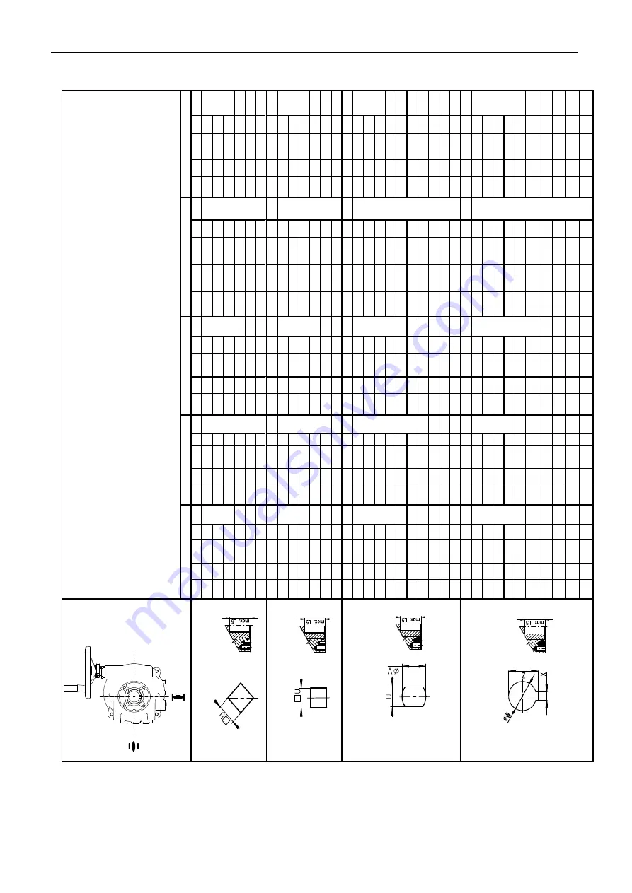
 UP 0, UP 1, UP 2,  UP 2.4, UP 2.5 


53 

Tv

ar

D

/

вид

D

/S

ha

pe

D

U

L5

U

L5

U

L5

U

L5

U

L5

D

-9

9

D

-9

9

D

-14

14

D

-11

11

D

-22

22

D

-11

11

D

-11

11

D

-17

17

D

-14

14

D

-27

27

D

-14

14

D

-12

12

D

-19

19

D

-16

16

D

-36

36

D

-14

14

D

-22

22

D

-17

17

D

-16

16

D

-22

22

D

-17

17

D

-27

27

Tv

ar

L

/

вид

L

/S

ha

pe

L

U

L5

U

L5

U

L5

U

L5

U

L5

L-9

9

L-9

9

L-

14

14

L-

11

11

L-

22

22

L-

11

11

L-

11

11

L-

17

17

L-

14

14

L-

27

27

L-

14

14

L-

12

12

L-

19

19

L-

16

16

L-

36

36

L-

16

16

L-

22

22

L-

17

17

L-

17

17

L-

22

22

L-

27

27

Tv

ar

H

/

вид

H

/S

ha

pe

H

U

V

L5

U

V

L5

U

V

L5

U

V

L5

U

V

L5

H-8

8

13

H

-8

8

13

H

-13

13

19

H

-8

8

13

H

-22

22

32

H-9

9

14

H

-10

10

16

H

-14

14

22

H-

10

10

16

H

-27

27

48

H

-11

11

14

H

-11

11

18

H

-17

17

36

H-

11

11

18

H

-36

36

48

H

-11

11

18

H

-13

13

19

H

-19

19

28

H-

13

13

19

H

-14

14

18

H

-14

14

22

H

-22

22

36

H-

14

14

22

H

-17

17

25

H-

16

16

22

H-

17

17

25

H-

19

19

28

H-

22

22

32

H-

27

27

48

Tv

ar

V

/

вид

V

/S

ha

pe

V

W

Z

X

L5

W

Z

X

L5

W

Z

X

L5

W

Z

X

L5

W

Z

X

L5

V-

12

12

13

,6

4

V-

17

17

19

,5

6

V-

17

17

19

,5

6

V-

17

17

19

,5

6

V-

42

42

45

,1

12

V-

14

14

16

,1

5

V-

18

18

20

,5

6

V-

18

18

20

,5

6

V-

18

18

20

,5

6

V-

50

50

53

,5

14

V-

18

18

20

,6

6

V-

20

20

22

,5

6

V-

22

22

24

,9

8

V-

20

20

22

,5

6

V-

48

48

51

,5

14

V-

30

30

32

,5

8

V-

28

28

30

,9

8

V-

22

22

24

,5

6

V-

60

60

64

,4

18

V-

36

36

39

,3

10

V-

28

28

30

,9

8

V-

40

40

43

,1

12

V-

42

42

45

,3

12

V-

30

30

32

,5

8

V-

32

,2

32

,2

35

6,5

V-

42

42

45

,1

12

V-

45

,4

45

,4

48

,8

10

V-

50

50

53

,5

14

TV

AR

 P

RIP

O

JO

VA

CI

EH

O

 D

IE

LC

PR

ES

Ф

О

РМА


ПР

И

СО

ЕД

И

НИ

ТЕЛ

ЬН

ОЙ


Д

ЕТ

АЛИ

/ C

O

U

PL

IN

G

 S

HA

PE

U

2.5

U

P 0

U

P 1

U

P 2

U

2.4

36

36

36

36

37

.5

37

.5

37

.5

70

70

70

70

37

.5

49

49

49

49

56

56

56

56

O

Z/

З

/C


Summary of Contents for UP 0

Page 1: ...74 0984 02 74 0984 02 INSTALLATION SERVICE AND MAINTENANCE INSTRUCTIONS Electric part turn actuators UP 0 UP 1 UP 2 UP 2 4 UP 2 5 ...

Page 2: ...od months Input operating signal Serial number of electric motor Serial number of transmitter Serial number of position controller Tests made in accordance with TP 74 1049 00 Tests made by Packed by Date Signature and stamp COMPLETENESS CERTIFICATE INSTALLATION CERTIFICATE Used valve Assembled by Firm Name Warranty period months Date Signature and stamp Location Installed by Firm Name Warranty per...

Page 3: ...mitter Fig 4 26 4 4 Adjustment of the Electronic Position Transmitter EPV the Resistive Transmitter Potentiometer with the Converter PTK 1 27 4 5 Adjustment of Capacitive Transmitter CPT1 A Fig 7 28 4 6 Adjustment of position controller Fig 13 30 4 7 Adjustment of the DCPT3M transmitter 32 4 8 Adjustment of the operating angle position and adjustment of stop screws Fig 10 14 33 5 Service and Maint...

Page 4: ...current Electric actuators are according to directive LVD 2014 35 EU and standard EN 61010 1 within valid edition assigned for installation category II overvoltage category pollution degree 2 The product meets the essential safety requirements according to EN 60204 1 and is in compliance with EN 55011 A1 within valid edition Product influence to environment Electromagnetic compatibility EMC the pr...

Page 5: ...uct which are stated in the Contract The supplier is not responsible for any deterioration of parameters caused by the customer during storage unauthorised installation or improper operation 1 5 Under guarantee and after guarantee service Our customers are provided with professional service of our firm in installation operation service maintenance revision and help in troubleshooting for all our p...

Page 6: ...ere When installed in the areas with relative humidity more than 80 in open air under a shelter is needed to connect the space heater directly without a thermal switch Installation and operation of EA is possible in any position Vertical position of output part axis and with the control part above the valve is usual 1 6 2 Working enviroment According to valid standard IEC 60 721 2 1 there are deli...

Page 7: ...urrent with intensity of magnetic field direct or alternate of mains frequency up to 400A m 1 AM 2 2 of sun radiation with intensity 500 and 700W m2 AN 2 with effects of medium seismic activity with acceleration 300 Gal 600 Gal AP 3 with direct endanger by storm AQ 2 with quick air movement and strong wind AR 3 AS 3 stand on a conductive bottom BC 3 without any danger media with object BE 1 Markin...

Page 8: ...ance with accompanying documentation or the Contract If any discrepancy or fault occur inform immediately your supplier If the actuators and accessories are not immediately installed they have to be stored in dry well ventilated sheltered rooms protected against dirt dust soil humidity with placing onto shelves or onto pallets chemical impacts and encroachment at ambient temperature from 10 C up t...

Page 9: ...The control part Fig 1 1a 1b 1c is placed on a control board 1 consisting of electric motor 2 at single phase version with capacitor torque unit 5 controlled with a worm axial shift position signaling unit 3 with a position transmitter 6 resistive capacitive or electronic position transmitter 7 and with a mechanical local position indicator 4 space heater 8 with thermal switch electronic module 9 ...

Page 10: ...8 UP 0 UP 1 UP 2 UP 2 4 UP 2 5 5 9 Fig 1a Fig 1b ...

Page 11: ...UP 0 UP 1 UP 2 UP 2 4 UP 2 5 9 Fig 1c UP 2 5 with controller ...

Page 12: ...ngle phase 115 60Hz 13 8 14 2 375 450 0 27 3 3 250 5 4 10 12 5 7 5 6 25 12 18 10 8 22 25 15 12 5 21 35 20 17 44 50 22 5 18 5 32 55 30 25 54 63 7 5 resp 8 5 6 2 resp 7 0 1500 resp 1800 1000 resp 1200 0 03 5 4 10 12 5 7 5 6 25 12 18 10 8 22 25 15 12 5 21 35 20 17 44 50 22 5 18 5 32 55 UP 0 type number 340 30 25 54 63 Three phase 3x400 3x380 50 60Hz 15 13 1500 resp 1800 1000 resp 1200 0 09 resp 0 105...

Page 13: ... 300 40 420 500 120 2600 1 0 8 450 80 160 680 800 230 220 60 2750 0 7 7 400 20 17 250 300 40 34 420 500 120 3100 2 0 8 450 80 66 160 128 680 800 Single phase 120 60Hz 70 3380 0 71 16 250 20 250 300 40 420 500 80 160 680 800 Single phase Direct current 24 AC DC 100 3350 4 9 20 250 300 40 420 500 180 2650 0 6 80 UP 2 4 type number 343 160 680 800 Three phase 3x400 3x380 resp 3x415 90 2740 0 35 20 34...

Page 14: ...from operating angle on nameplate Adjustment of the torque switches If other adjustment not specified the switching torque is set to the maximum value with tolerance of 10 Readjustment of EA s UP 0 switching off torque is not possible to do at customer s house Switches S1 S2 S3 S4 S5 S6 UP 0 Type DB 6 equipped with the sliver contacts standard version 250 V AC 20mA 2 A cosϕ 0 6 24 V and 48 V DC 20...

Page 15: ...ometer values at limit positions O open 93 Z closed 5 from the real value of the resistance Capacitive B3 non contact life 108 cycles 2 wire connection with built in power supply or without built in power supply The current signal 4 20 mA DC is acquired from the capacitive transmitter supplied from the internal or an external voltage supply source The electronics of the transmitter is protected ag...

Page 16: ...r UP 0 max 3 kΩ Load resistance for 3 wire version 0 20mA for UP 0 max 750 Ω Load resistance for 3 wire version 0 10 V for UP 0 max 10 kΩ Temperature dependency max 0 020 mA 10 C Output signal values at limit positions on the terminal 81 82 O 20 mA 5 mA 10 V Z 0 mA 4 mA 0 V Values tolerance of output signal Z 1 5 1 O 1 5 1 Linearity deviation 2 5 1 Hysteresis max 2 5 1 1 from rated value of transm...

Page 17: ... mode error message LED Adjusters communication connector 2x calibrating and adjusting button Lubricators see chapter Maintenance extent and periodicity 2 2 1 Mechanical connection flange ISO 5211 Basic and connecting dimensions are given in dimensional drawings 2 2 2 Electrical connection Terminals X for EA UP 0 max 24 screw less terminals with connecting wire cross section of 0 08 to 1 5 mm 2 Te...

Page 18: ...t protection We recommend to use fuses for protection of product Table 4 Fuse values and characteristics Type Order code Voltage Frequency Hz Electric motor Power Power input W max curent EA A Fuse values F3 340 X 0XXXX YY 230 VAC 340 X LXXXX YY 220 VAC 50 0 22 T 0 500 A 250 V UP 0 340 340 X 3XXXX YY 24 VAC 50 60 13 8 31 2 2 T 3 15 A 250 V 341 X 0XXXX YY 230 VAC 341 X LXXXX YY 220 VAC 50 40 90 0 8...

Page 19: ...UP 0 UP 1 UP 2 UP 2 4 UP 2 5 17 Electric connection according to the wiring diagram stuck into the case of the EA OUTSIDE GROUNDING TERMINAL Fig 1c INSIDE GROUNDING TERMINAL Fig 1d ...

Page 20: ...gear carefully Lubricate the output shaft of the valve gear with a grease not containing any acids Set the EA to the limit position closed set the valve to the same position Put the EA onto the valve with the output shaft reliably stalled in the valve coupling gear Exchange of the mechanical connection flange from F05 to F07 applies only to ES UP 1 Push the insert fig 1e 1 and the stop tube 2 out ...

Page 21: ...ral transmitters their number depends on current which the source can supply Connection with the terminal board Before the connection remove the actuator case and check whether the type of current power supply and frequency correspond with the data on the actuator nameplate Electric connection The electric connection should be realized according to the wiring diagram stuck into the case of the EA ...

Page 22: ...contacts resulting in their sticking together After adjustment of the actuator check its operation using the control circuit Especially make sure that the actuator starts up correctly and that the electric motor is disconnected from power supply after triggering of the corresponding micro switch Otherwise immediately disconnect the power supply to the actuator to prevent damage to the electric mot...

Page 23: ...s potential electrical accident Disconnect the EA from mains Disconnect the leads from the EA terminal boards and loosen the cables from cable glands Pull out the connectors in case of the connector version Loosen the fixing screws of the EA flange and coupling screws and disconnect the EA from the valve While sending the EA to be repaired put it into a package solid enough to avoid damages of the...

Page 24: ... clockwise direction when looking into the actuator control part from the top 4 1 Adjustment of the torque unit The switching off torque are adjusted by the producer for both directions i e for the direction opening the torque switch S1 as well as for the direction closing the torque switch S2 to the specified value with tolerance of 10 If not stated else they are adjusted to the maximum rate It i...

Page 25: ...h create axial thrust reset the EA to the Open position and rotate the cam 29 clockwise when viewing the actuating plate from above until switch S3 switches over 25 reset the EA by the angle where the Open position is to be indicated and turn the cam 31 clock wise until switch S3 switches over 27 reset the EA to the Closed position and turn the cam 28 counter clockwise until switch S4 switches ove...

Page 26: ...activated when moving towards open position and rotate cam V5 in the clockwise direction until switch S5 is activated Reset the actuator to the position at which you want the S6 signaling switch to be activated when moving towards closed position and rotate cam V6 in counter clockwise direction until switch S6 is activated Rotate the position indicator discs for the particular stroke with respect ...

Page 27: ...ted in series see the wiring diagram UP 0 If the valve needs to be tightly closed in the limit position by thrust in the corresponding direction it is necessary to align the corresponding position switch S3 or S4 so that it does not get activated before the switching off torque is reached Observe the valve manufacturer s instructions when aligning the actuator with the valve Fig 3a Position indica...

Page 28: ...of 100 Ω resistance is used To adjust the transmitter follow these steps Loosen the fixing screws 9 of the transmitter holder and push the transmitter out of mesh Put the actuator to the position closed with the handwheel until the corresponding position switch S2 or S4 switches Connect a meter for resistance measuring to the terminals 71 and 73 For the transmitter RP 19 rotate the transmitter sha...

Page 29: ...ansmitter according to the previous chapter The resistance is to be metered on the terminals X Y resp R R Fig 5 5a The used transmitter resistance is 100 Ω Switch the converter s power supply on Turn the adjusting trimmer ZERO resp A to adjust the output current signal rate measured on the terminals 81 82 to 4 mA Set the actuator to the position open Turn the adjusting trimmer GAIN resp B to adjus...

Page 30: ...chapter describes adjustment of the capacitive transmitter to the specified parameters standard values of output signals in case they are reset The capacitive transmitter 95 serves as a position transmitter of electric actuators with unified output signal of 4 20 mA in electric actuators UP X X or as a feedback of a position controller or if required it functions also as a remote position transmit...

Page 31: ...onnect a mA meter of precision class 0 5 and loading resistance lower than 500 Ω on the terminals 81 82 Follow the procedure described in the previous chapter A The user has to arrange grounding of the 2 wire circuit of the capacitive transmitter to the electrical ground of a joined controller computer etc The grounding should be performed only in one place in any part of the circuit outside the e...

Page 32: ...the position transmitter before adjustment of the controller In addition it is necessary to monitor the correct running of the electric motor concerning the sequence number of phases otherwise it may happen that during automatic calibration the engine will run in the opposite direction and the controller will not detect this as an error Laying of adjusters and signaling elements on the board of th...

Page 33: ...the positions open and closed measures inertia mass in the directions opening and closing and loads the adjusted parameters into the EEPROM memory In case that during the initialization process an error occurs e g in connection or adjustment the initialization process will be interrupted and the controller with the D4 diode reports about the type of the error Else after finishing the initializatio...

Page 34: ...ons are within 35 to 100 of the rated stroke specified in the nameplate If necessary please change the characteristic of the output signal from descending to ascending or vice versa according to the following chapter 4 7 2 Setting of the ascending descending characteristic of the output signal When the characteristic of the transmitter output signal is changed the set limit positions 4 mA and 20 m...

Page 35: ...l value is saved To increase the current value press 4 By holding the button depressed auto repeat is activated to continuously increase the value of the output current and when the button is released the actual value is saved 4 7 4 Transmitter error messages Error is indicated by flashing LED The number of repeated LED flashes indicates the error code as per table 5 TABLE 5 Number of LED flashes ...

Page 36: ...le they allow to change this position from Z 0 and from position O 60 90 120 160 by value 10 whilst the operating angle amount specified on the EA type plate must remain unchanged Adjusting of stroke 90 without changed position of operating angle 0 Fig 10 SCREW FOR POSITION Z SCREW FOR POSITION O a b ...

Page 37: ...kwards as minimum to avoid sooner connection from the torque unit perform similar adjustment of the backstop screw for position O open 4 8 2 Adjusting of backstop screws during switching off the EA from torque When using the backstop screws as endpoints backstops for the EA output shaft path thus the EA must have the torque unit adjusted in such way that no overrunning of the switching off torque ...

Page 38: ...ase Fig 13 or decrease Fig 14 the operating angle by 26 on adjusted EA by means of backstop screws but you are loosing possibility of the output shaft position tuning In doing so the positioning unit must be adjusted to this angle and transmitter must be ejected from angle Adjustment of elevation angle 70 reduction of the operating angle by 20 Fig 14 a b Adjustment of elevation angle 110 increasin...

Page 39: ...tions is four years The replacement of cover gaskets and gasket of an oil filling is needed in case of damage or after 6 years of the operation The grease in the supplied actuators is designed for the lifetime of the product It is not necessary to change the grease during the operation of the actuator During inspection replace the sealing O ring see Chapter 6 between the bottom and top cover repla...

Page 40: ...here are no revolutions of motor rotor when operating the push buttons 2 No voltage on the control part Check connection of the control part 1 Incorrect setting up of the switches Perform adjustment The EA fails to stop at the limit positions 2 The microswitch is defective Replace the microswitch for a new one and adjust The EA stops at the mid position There is an obstacle in the valve or part of...

Page 41: ...X 2 1 Electric motor 15 W 3x400 V AC 50Hz 3x400V AC UP 0 63 592 XXX 2 1 Electric motor 13 W 3x400 V AC 60Hz 3x400V AC UP 0 63 592 XXX 2 1 Capacitor 0 82µF UP 0 63 540 002 63 540 007 2 1 Capacitor 82µF UP 0 63 540 006 63 540 003 2 1 Capacitor 5µF UP 1 63 540 001 2 1 Capacitor 7µF UP 2 UP 2 4 UP 2 5 63 540 181 2 1 Capacitor 8µF UP 2 UP 2 4 UP 2 5 Motor component 2 1 Capacitor 3 3µF UP 0 63 542 038 2...

Page 42: ...40 UP 0 UP 1 UP 2 UP 2 4 UP 2 5 7 Enclosures 7 1 Wiring diagrams UP 1 UP 2 UP 2 4 UP 2 5 ...

Page 43: ...UP 0 UP 1 UP 2 UP 2 4 UP 2 5 41 ...

Page 44: ...42 UP 0 UP 1 UP 2 UP 2 4 UP 2 5 Wiring diagrams UP 0 ...

Page 45: ...agram with controller with current feedback for 1 phase electric motor Z41a wiring diagram of space heater and space heater s thermal switch connection Z21a wiring diagram of additional position switches connection B1 resistive transmitter potentiometer single B2 resistive transmitter potentiometer double B3 capacitive transmitter S1 torque switch open S2 torque switch closed S3 position switch op...

Page 46: ...8 19 20 S3 20 22 23 24 S4 24 26 27 28 S5 28 30 31 32 S6 32 34 35 36 ReS11 36 38 39 40 ReS12 40 42 Contact connected Contact disconnected Note 1 Signaling from switches S5 S6 for EA UP 0 is possible from 50 of the maximum operating stroke adjusted mentioned in the nameplate before end position If Note 2 Switches contacts brought out according to exact wiring diagram ...

Page 47: ...UP 0 UP 1 UP 2 UP 2 4 UP 2 5 45 7 4 Dimensional drawings Electric part turn actuators Unimact UP 0 UP 1 UP 2 ...

Page 48: ...46 UP 0 UP 1 UP 2 UP 2 4 UP 2 5 Electric part turn actuators Unimact UP 0 UP 1 UP version stand and lever ...

Page 49: ...UP 0 UP 1 UP 2 UP 2 4 UP 2 5 47 Electric part turn actuators Unimact UP 1 UP 2 version with local control ...

Page 50: ...48 UP 0 UP 1 UP 2 UP 2 4 UP 2 5 Electric part turn actuators Unimact UP 1 UP 2 version with local control stand and lever ...

Page 51: ...UP 0 UP 1 UP 2 UP 2 4 UP 2 5 49 Electric part turn actuators Unimact UP 2 4 UP 2 5 ...

Page 52: ...50 UP 0 UP 1 UP 2 UP 2 4 UP 2 5 Electric part turn actuators Unimact UP 2 4 UP 2 5 version stand and lever ...

Page 53: ...UP 0 UP 1 UP 2 UP 2 4 UP 2 5 51 Electric part turn actuators Unimact UP 2 4 UP 2 5 version with local control ...

Page 54: ...52 UP 0 UP 1 UP 2 UP 2 4 UP 2 5 Electric part turn actuators Unimact UP 2 4 UP 2 5 version with local control stand and lever ...

Page 55: ...8 H 36 36 48 H 11 11 18 H 13 13 19 H 19 19 28 H 13 13 19 H 14 14 18 H 14 14 22 H 22 22 36 H 14 14 22 H 17 17 25 H 16 16 22 H 17 17 25 H 19 19 28 H 22 22 32 H 27 27 48 TvarV видV ShapeV W Z X L5 W Z X L5 W Z X L5 W Z X L5 W Z X L5 V 12 12 13 6 4 V 17 17 19 5 6 V 17 17 19 5 6 V 17 17 19 5 6 V 42 42 45 1 12 V 14 14 16 1 5 V 18 18 20 5 6 V 18 18 20 5 6 V 18 18 20 5 6 V 50 50 53 5 14 V 18 18 20 6 6 V 2...

Page 56: ...UP 0 UP 1 UP 2 UP 2 4 UP 2 5 Pull rod TV 160 P 0100 Pull rod TV 360 P 0210 Pull rod TV 40 1 20 a TV 50 1 25 Version Pull rod version A B D P 1413 A TV 40 1 20 23 20 P 1413 B TV 50 1 25 28 Max 50 Min 30 25 ...

Page 57: ... service check report Service center Date of repair Guarantee repair no User of actuator Claim applied by Actuator type number Actuator production number Product claim fault Detected product fault Used spare parts Remarks Issued on a day Signature ...

Page 58: ...7 6 Post guarantee service check report Service center Date of repair User of actuator Actuator operating place Actuator type number Actuator production number Detected product fault Used spare parts Remarks Issued on a day Signature ...

Page 59: ...UP 0 UP 1 UP 2 UP 2 4 UP 2 5 57 7 7 Commercial representation Slovak Republic Regada s r o Strojnícka 7 080 01 Prešov Tel 421 0 51 7480 460 Fax 421 0 51 7732 096 E mail regada regada sk ...

Reviews: