


Installation
6
—
English
Fillcontrol Auto
—
22.09.2020 - Rev. C
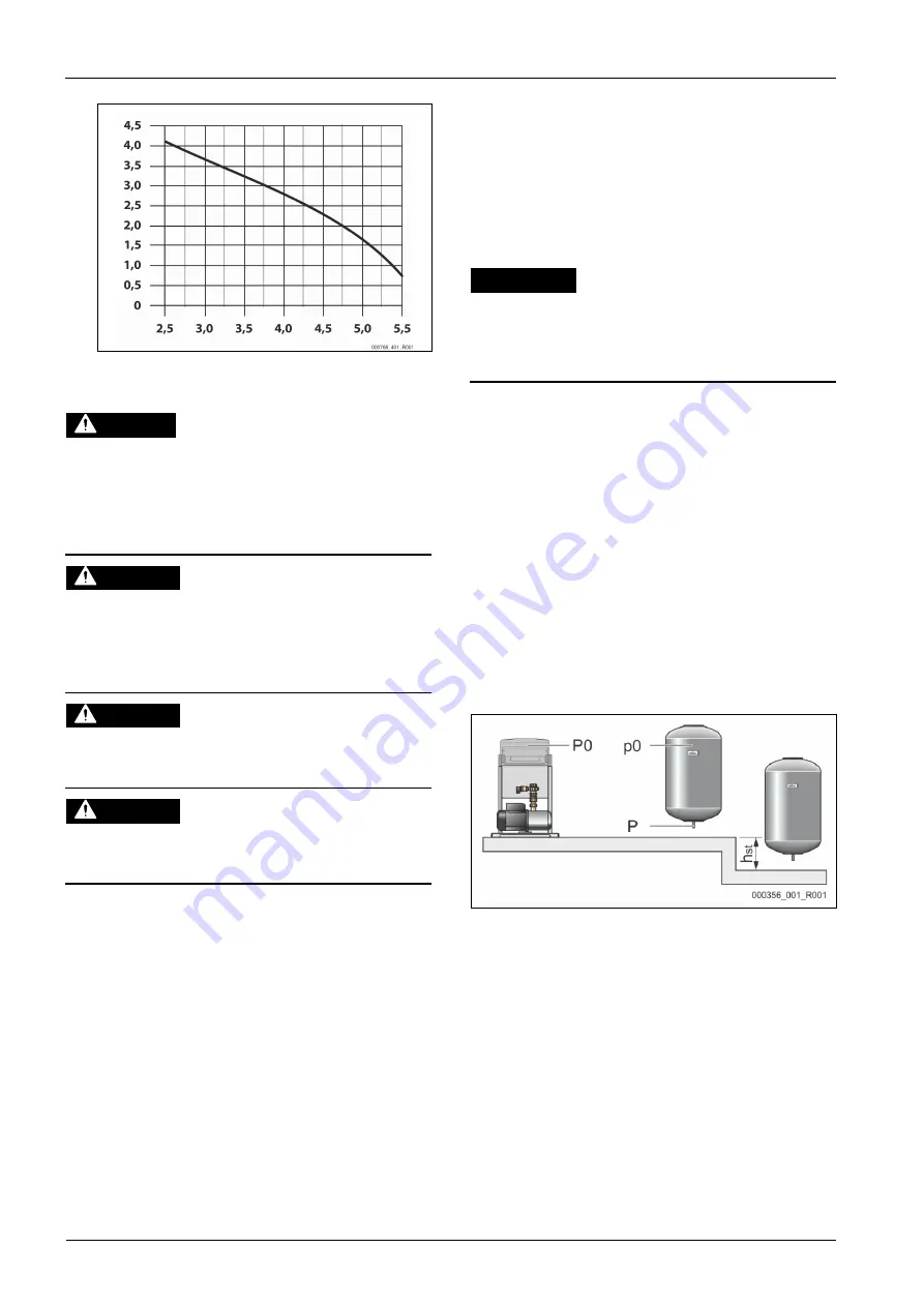
Performance chart
Ma
ke
-up
ca
pa
ci
ty
in
m
3
/h
our
Make-up pressure in bar
6
Installation
DANGER
Risk of serious injury or death due to electric shock.
If live parts are touched, there is risk of life-threatening injuries.
•
Ensure that the system is voltage-free before installing the device.
•
Ensure that the system is secured and cannot be reactivated by other
persons.
•
Ensure that installation work for the electric connection of the device is
carried out by an electrician, and in compliance with electrical
engineering regulations.
CAUTION
Risk of injury due to pressurised liquid
If installation, removal or maintenance work is not carried out correctly, there
is a risk of burns and other injuries at the connection points, if pressurised
hot water or hot steam suddenly escapes.
•
Ensure proper installation, removal or maintenance work.
•
Ensure that the system is de-pressurised before performing installation,
removal or maintenance work at the connection points.
CAUTION
Risk of burns on hot surfaces
Hot surfaces in heating systems can cause burns to the skin.
•
Wear protective gloves.
•
Please place appropriate warning signs in the vicinity of the device.
CAUTION
Risk of injury due to falls or bumps
Bruising from falls or bumps on system components during installation.
•
Wear personal protective equipment (helmet, protective clothing,
gloves, safety boots).
Note!
Confirm that installation and start-up have been carried out correctly
using the installation and commissioning certificate. This action is a
prerequisite for the making of warranty claims.
–
Have the Reflex Customer Service carry out commissioning and
the annual maintenance.
6.1
Installation conditions
6.1.1
Incoming inspection
Prior to shipping, this device was carefully inspected and packed. Damages
during transport cannot be excluded.
Proceed as follows:
1.
Upon receipt of the goods, check the shipment for
•
completeness and
•
possible transport damage.
2.
Document any damage.
3.
Contact the forwarding agent to register your complaint.
6.2
Preparatory work
Preparing the device installation:
•
Frost-free, well-ventilated room.
–
Room temperature range: 0 °C to 35 °C.
•
Filling connection.
–
If necessary, provide a DN 15 filling connection according to
DIN 1988 T 4.
•
Electric connection: 230 V~, 50 Hz, 16 A with upstream ELCB: Tripping
current 0.03 A.
6.3
Execution
ATTENTION
Damage due to improper installation
Additional device stresses may arise due to the connection of pipes or system
equipment.
•
Ensure that pipes are connected from the device to the system without
them being stressed or strained.
•
If necessary, provide support structures for the pipes or equipment.
Note!
Starting up of the pump causes vibration in the device. This transfers
loud noises into the system pipes.
–
Connect the pipes to the device using flexible connections.
In systems with a diaphragm expansion tank, the device must be installed in the
vicinity of the tank. To ensure that the required filling pressure for water make-
up is recorded by the pressure transducer in the device. The filling pressure
depends on the minimum operating pressure of the facility system. For
calculating the minimum operating pressure, see chapter 7.2 "Determining the
P
minimum operating pressure for the controller" on page 9 .
Proceed as follows for the installation:
1.
Position the device.
2.
Create the water-side connections of the device to the system.
–
Use connections with the same dimensions at the device for all lines.
3.
If required, create the interfaces according to the terminal plan.
6.3.1
Floor mounting
The device is installed on the floor. Select the attachment means according to
the floor properties.
Comply with the following instructions:
•
The device is installed sufficiently close to the diaphragm expansion vessel.
You ensure so that the "PIS" pressure sensor is able to measure the filling
pressure.
•
That it is possible to open and close the valves.
•
Ensure sufficient space for installing the connection lines.
Note!
The "h
st
" static height is required to determine the minimum operating
pressure of the system circuit.


