
16
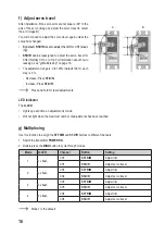
f) Adjust servo travel
After installation, if the servo arms are not square / 90° to the
axis of the servo (image A), adjust the servo travel to center
the arm image B).
You will not need to adjust the servo travel again unless the
setup has changed.
• By default, ST.D/R is set to adjust the trim for CH1 (steer-
ing).
• ST.D/R can be
reassigned to adjust the servo travel for
CH2 (throttle), CH3, or CH4. For information about how to
reassign, see "g) Multiplexing" on page 16.
• The adjustment range is: 0 to 120% (default 100%), each
step is 5 %.
- Decrease: Press ST.D/R-
- Increase: Press ST.D/R+
Press and hold for rapid adjustments.
1
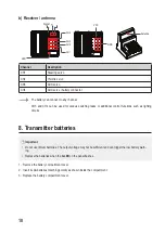
LED indicator
The G.LED:
• Lights up each time an adjustment is made.
• Will not light when the maximum number of adjustments has been reached.
g) Multiplexing
Use this function to assign the ST.TRIM and ST.D/R buttons to different channels.
1. Switch the transmitter POWER ON.
2. Double-press the BIND button to cycle through modes.
Mode
G.LED
Channel
Button
Setting
1
1x flash
CH1
ST.TRIM
Adjust trim
CH1
ST.D/R
Adjust servo travel
2
2x flash
CH1
ST.TRIM
Adjust trim
CH2
ST.D/R
Adjust servo travel
v
3
3x flash
CH3
ST.TRIM
Adjust trim
CH3
ST.D/R
Adjust servo travel
v
4
4x flash
CH4
ST.TRIM
Adjust trim
CH4
ST.D/R
Adjust servo travel
Mode 1 is the default
A
B


