red lion PAXDP User Manual Download Page 23

23

1

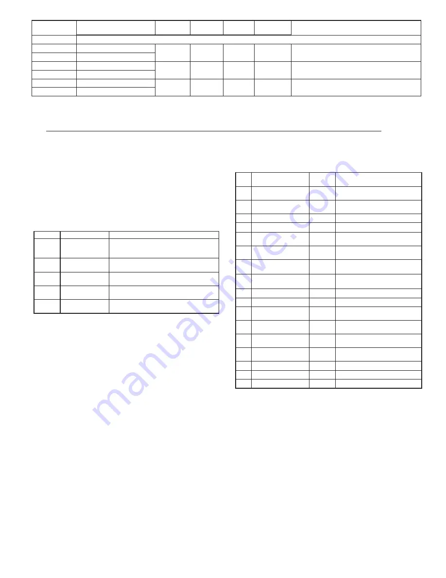
  For Input Registers, replace the 4xxxx with a 3xxxx in the above register address. The 3xxxx are a mirror of the 4xxxx Holding Registers.

2

  An attempt to exceed a limit will set the register to its high or low limit value.

400

300

200

99999

99999

99999

-19999

-19999

-19999

Alternate Setpoint 4 Value (Hi word)

Alternate Setpoint 3 Value (Hi word)

Alternate Setpoint 2 Value (Hi word)

Alternate Setpoint 4 Value (Lo word)

Alternate Setpoint 3 Value (Lo word)

Alternate Setpoint 2 Value (Lo word)

40047

40045

40043

40048

40046

40044

Setpoint List B

Setpoint List B

Setpoint List B

FREQUENTLY USED REGISTERS (Continued)

COMMENTS

ACCESS

FACTORY 

SETTING 

HIGH LIMIT 

2

LOW LIMIT 

2

REGISTER NAME

REGISTER  

ADDRESS 

1

Read/Write

Read/Write

Read/Write

SERIAL RLC PROTOCOL COMMUNICATIONS

RLC Communications requires the Serial Communications Type Parameter 

(



) be set to 



.

SENDING SERIAL COMMANDS AND DATA

When sending commands to the meter, a string containing at least one 

command character must be constructed. A command string consists of a 

command character, a value identifier, numerical data (if writing data to the 

meter) followed by a the command terminator character * or $.

Command Chart

COMMAND DESCRIPTION

NOTES

N

Node (Meter) 

Address Specifier

Address a specific meter. Must be followed by 

a one or two digit node address. Not required 

when address = 0.

T

Transmit Value 

(read)

Read a register from the meter. Must be 

followed by register ID character

V

Value Change 

(write)

Write to register of the meter. Must be followed 

by register ID character and numeric data.

R

Reset

Reset a register or output. Must be followed by 

register ID character.

P

Block Print Request 

(read)

Initiates a block print output. Registers are 

defined in programming.

Command String Construction

The command string must be constructed in a specific sequence. The meter 

does not respond with an error message to invalid commands. The following 

procedure details construction of a command string:
1. The first characters consist of the Node Address Specifier (N) followed by a 

1 or 2 character address number. The address number of the meter is 

programmable. If the node address is 0, this command and the node address 

itself may be omitted. This is the only command that may be used in 

conjunction with other commands. 

2. After the address specifier, the next character is the command character.

3. The next character is the Register ID. This identifies the register that the 

command affects. The P command does not require a Register ID character. 

It prints according to the selections made in print options.

4. If constructing a value change command (writing data), the numeric data is 

sent next. 

5. All command strings must be terminated with the string termination 

characters * or $. The meter does not begin processing the command string 

until this character is received. See Timing Diagram figure for differences 

between terminating characters.

Register Identification Chart

1. Register Names are also used as Register Mnemonics during full transmission.
2. The registers associated with the P command are set up in Print Options 

(Module 7). Unless otherwise specified, the Transmit Details apply to both T 

and V Commands.

Command String Examples:

1. Address = 17, Write 350 to Setpoint 1 

String: N17VM350*

2. Address = 5, Read Input A value

String: N5TA*

3. Address = 0, Reset Setpoint 4 output

String: RS*

Transmitting Data To the Meter

Numeric data sent to the meter must be limited to Transmit Details listed in 

the Register Identification Chart. Leading zeros are ignored. Negative numbers 

must have a minus sign. The meter ignores any decimal point and conforms the 

number to the scaled resolution. (ie. The meter’s scaled decimal point position  

is set for 0.0 and 25 is written to a register. The value of the register is now 2.5. 

In this case, write a value of 250 to equal 25.0).

Note: Since the meter does not issue a reply to value change commands, follow 

with a transmit value command for readback verification.

OFB

SOR

Input B Offset

Setpoint Register

J

X

OFA

AOR

Input A Offset

Analog Output Register

I

W

ABB

MMR

Auto/Manual Register

U

ABA

SP4

Setpoint 4

G

S

MAX

SP3

Max

Setpoint 3

F

Q

MIN

SP2

Min

Setpoint 2

E

O

TOT

SP1

Total

Setpoint 1

D

M

CLC

Calculation Value

C

INB

B

INA

A

REGISTER 

NAME 

1

VALUE DESCRIPTION

ID

COMMAND SUPPORTED

2

T
T, R (reset command zeros Total)

T

T, V

T

T, V

T, V

T, V

T, V

T, R (reset command zeros  

or tares input)
T, R (reset command zeros  

or tares input)

Input A Absolute 

(Gross) Value
Input B Absolute 

(Gross) Value

T, V, R (reset command resets 

setpoint output)
T, V, R (reset command resets 

setpoint output)
T, V, R (reset command resets 

setpoint output)
T, V, R (reset command resets 

setpoint output)

Input A  

Relative Value
Input B  

Relative Value

T, R (reset command loads  

current reading)
T, R (reset command loads  

current reading)

Summary of Contents for PAXDP

Page 1: ...eadout of totalized flow calculate service intervals of motors or pumps etc The totalizer can also accumulate batch operations The meter has four setpoint outputs implemented on Plug in option cards T...

Page 2: ...S30 Quad Setpoint Sourcing Open Collector Output Card PAXCDS40 PAXCDC RS485 Serial Communications Card with Terminal Block PAXCDC10 Extended RS485 Serial Communications Card with Dual RJ11 Connector P...

Page 3: ...Response Time 20 msec max Logic State Jumper selectable for sink source logic 12 TOTALIZER Function Time Base second minute hour or day Batch Can accumulate gate input display from a user input Time...

Page 4: ...lude PAXCDS10 Dual Relay FORM C Normally open closed PAXCDS20 Quad Relay FORM A Normally open only PAXCDS30 Isolated quad sinking NPN open collector PAXCDS40 Isolated quad sourcing PNP open collector...

Page 5: ...rature and provides good air circulation Placing the unit near devices that generate excessive heat should be avoided The bezel should be cleaned only with a soft cloth and neutral soap product Do NOT...

Page 6: ...to the unit as possible Loop the cable through the core several times or use multiple cores on each cable for additional protection Install line filters on the power input cable to the unit to suppres...

Page 7: ...In order to preserve the safety of the meter application the sensor input common must be suitably isolated from hazardous live earth referenced voltages or input common must be at protective earth gro...

Page 8: ...device between appropriate User Input terminal and User Comm DSP 8 8 8 8 8 A C B PAR F1 F2 RST A 1 S P S P S 2 3 P P4 S Display Readout Legends Optional Custom Units Overlay Setpoint Alarm Annunciato...

Page 9: ...listed on the Parameter Value Chart following the programming section ALTERNATING SELECTION DISPLAY In the module description sections which follow the dual display with arrows appears for each progra...

Page 10: ...less than the band value the filter engages again This allows for a stable readout but permits the display to settle rapidly after a large process change The value of the band is in display units ind...

Page 11: ...mA 0 with 20 mA the desired high Display Value The calculations stop at the limits of the Input Range Jumper position 6 For input levels beyond the last programmed Input Value the meter extends the D...

Page 12: ...B Display will normally show the Relative unless switched by this function The Absolute is a gross value based on Module 1 DSP and INP entries without the Display Offset Value The Absolute display is...

Page 13: ...ECTIONS Select main or alternate setpoints Reset Setpoint 1 Alarm 1 Reset Setpoint 2 Alarm 2 Reset Setpoint 3 Alarm 3 Reset Setpoint 4 Alarm 4 Reset Setpoint 3 4 Alarm 3 4 Reset Setpoint 2 3 4 Alarm 2...

Page 14: ...s to be viewed and modified This Programming Mode can be locked with a security code and or user input When locked and the PAR key is pressed the meter enters a Quick Programming Mode In this mode the...

Page 15: ...present MAX value for the entered delay time the meter will capture that display value as the new MAX reading A delay time helps to avoid false captures of sudden short spikes to sec MAX CAPTURE ASSIG...

Page 16: ...ut permits the display to settle rapidly after a large process change The value of the band is in display units independent of the Display Decimal Point position A band setting of 0 keeps the digital...

Page 17: ...Totalizer Decimal Point parameter TOTALIZER HIGH ORDER DISPLAY When the total exceeds 5 digits the front panel annunciator flashes if assigned to A B or C display In this case the meter continues to t...

Page 18: ...with unbalanced hysteresis Deviation high with unbalanced hysteresis Deviation low with unbalanced hysteresis Inside band with unbalanced hysteresis Outside band with unbalanced hysteresis Lower Total...

Page 19: ...0 0 allows the meter to update the alarm status per the response time listed in the Specifications When the output logic is this becomes on time delay Any time accumulated at power off resets during p...

Page 20: ...not be used The PAXCDC1 RS485 or PAXCDC2 RS232 card should be used instead COMMUNICATIONS TYPE RLC Protocol ASCII Modbus RTU Modbus ASCII The Communication Type factory settings must be changed from...

Page 21: ...udes read only registers then only the write registers will change 4 If the write value exceeds the register limit see Register Table then that register value changes to its high or low limit FC17 Rep...

Page 22: ...o word N A N A N A Read Only 40003 Input B Relative Value Hi word N A N A N A Read Only 40004 40005 40006 40007 40009 40011 40013 40017 40015 40019 40008 40010 40012 40014 40018 40016 40020 Calculatio...

Page 23: ...ess specifier the next character is the command character 3 The next character is the Register ID This identifies the register that the command affects The P command does not require a Register ID cha...

Page 24: ...ot change the corresponding output mode U abcde e Analog Output d SP4 c SP3 b SP2 a SP1 Example VU00011 places SP4 and Analog in manual Analog Output Register AOR ID W This register stores the present...

Page 25: ...RMAT Data is transferred from the meter through a serial communication channel In serial communications the voltage is switched between a high and low level at a predetermined rate baud rate using ASC...

Page 26: ...E ANALOG UPDATE TIME to to to Enter the source for the analog output to retransmit Relative net Input Value The Relative Input Value is the Absolute Input Value that includes the Display Offset Value...

Page 27: ...ve selections to be calibrated At each prompt use the PAX arrow keys to adjust the external meter display to match the selection being calibrated When the external reading matches or if this range is...

Page 28: ...K Power level power connections Module 3 programming NO DISPLAY REMEDIES PROBLEM For further assistance contact technical support at the appropriate company numbers listed PARAMETER VALUE CHART Progra...

Page 29: ...RE ASSIGNMENT CALCULATION CONSTANT VALUE CALCULATION FUNCTION MIN CAPTURE DELAY TIME INPUT B OFFSET VALUE MAX CAPTURE DELAY TIME INPUT A OFFSET VALUE CALCULATION FILTER BAND DISPLAY INTENSITY LEVEL US...

Page 30: ...SP t LO t LO AS HI AS HI t SCFAC ASIN dECPt dECPt tbASE Locut P uP PAr INP A CALC INP b tYPE dAtA bAUd SPNt HILO tot Addr dELAY YES Abru OPt NO RLC MODE ONLY ASn n Scaling Style FUNCTION KEYS USER INP...

Page 31: ...31 This page intentionally left blank...

Page 32: ...Buyer its employees or sub contractors are or may be to any extent liable including without limitation penalties imposed by the Consumer Product Safety Act P L 92 573 and liability imposed upon any p...

Reviews: