


-9-
Released 2018-01-16
Drawing No. LP0749
The
selection allows the
SEL
key to toggle through the enabled
displays.
FRONT PANEL DISPLAY SELECT ENABLE (SEL)
5.3 MoDule 3 - D
IsPlay
anD
F
ront
P
anel
K
ey
P
araMeters
(
)
PAR
Front Panel
Reset Enable
Display Scroll
Enable
Programming
Security
Code
Display
Intensity
Level
Display
Select
Enable
Factory
Service
Operations
PARAMETER MENU
The
selection allows the
RST
key to reset the selected counter(s).
The shaded selections are only active when Counter B is enabled (Dual
Count Mode or batch counter).
FRONT PANEL COUNTER RESET ENABLE (RST)
The
selection allows the display to automatically scroll through the
enabled displays. Each display is shown for 4 seconds.
DISPLAY SCROLL ENABLE
Enter the desired Display Intensity Level (1-5). The display will actively
dim or brighten as levels are changed.
DISPLAY INTENSITY LEVEL
The Security Code determines the programming mode and the
accessibility of programming parameters. This code can be used along with
the Program Mode Lock-out (
) in the User Input Function parameter
(Module 1).
Two programming modes are available. Full Programming mode allows
all unit parameters to be viewed and modified. Quick Programming mode
permits only user selected values to be modified, but allows direct access
to these values without having to enter Full Programming mode.
Entering a Security Code from 1-99 enables Quick Programming mode, and
displays a sublist to select which values appear in the Quick Programming
menu. All of the values set to
in the sublist are accessible in Quick
Programming. The values include Setpoints (
,
), Output Time-outs
(
,
), Count Load value (
) and Display Intensity (
).
Programming any Security Code other than 0, requires this code to be
entered at the
prompt in order to access Full Programming mode. Quick
Programming mode, if enabled, is accessed before the
prompt appears.
USER INPUT
FUNCTION
USER INPUT
STATE
SECURITY
CODE
MODE WHEN “PAR”
KEY IS PRESSED
FULL PROGRAMMING
MODE ACCESS
not
______
0
Full Programming
Immediate Access
1-99
Quick Programming
After Quick
Programming with
correct code entry
at
prompt *
100-999
prompt
With correct code
entry at
prompt *
Active
0
Programming Lock
No Access
1-99
Quick Programming
No Access
100-999
prompt
With correct code
entry at
prompt *
Not Active
0-999
Full Programming
Immediate Access
* Entering Code 222 allows access regardless of security code.
PROGRAMMING SECURITY CODE
to
to
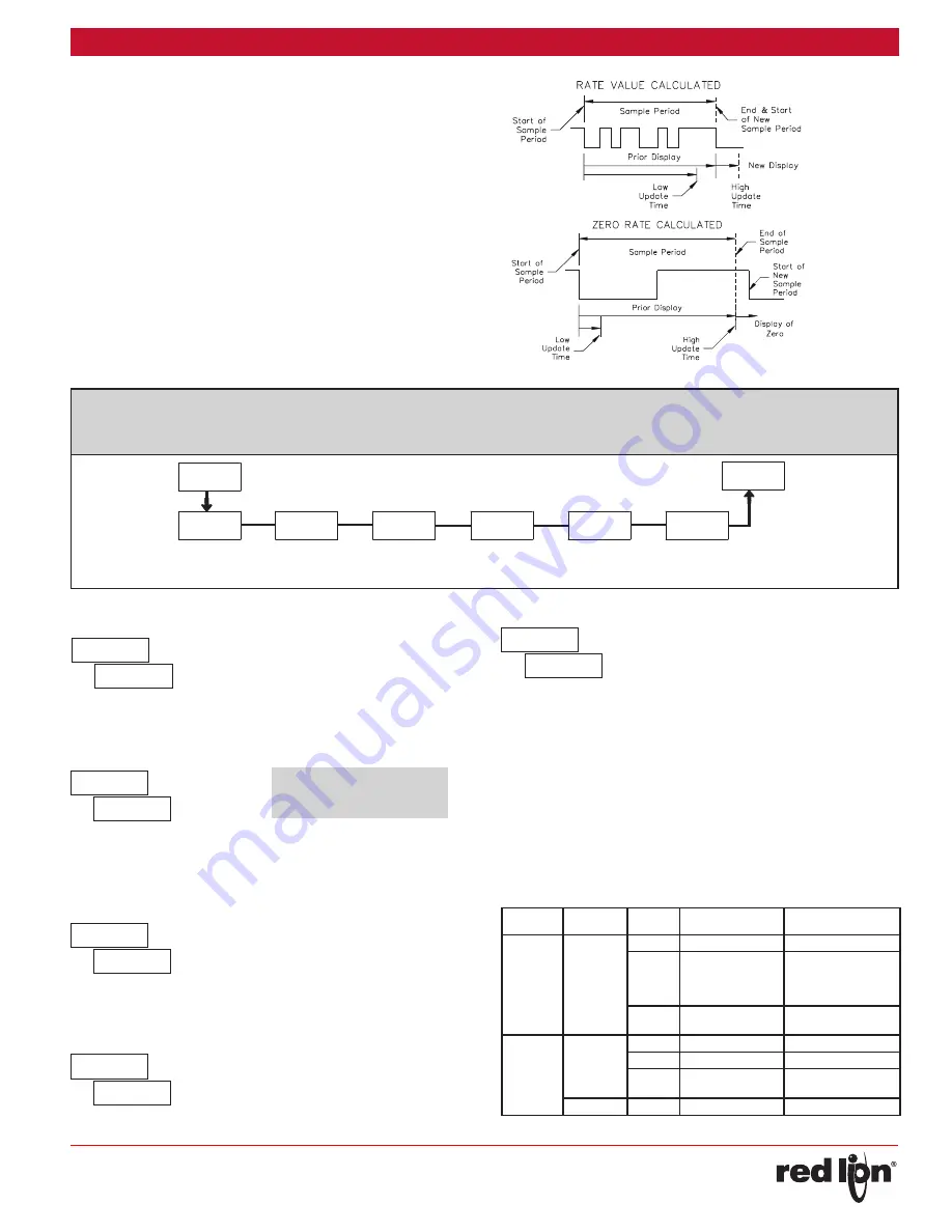
INPUT FREQUENCY CALCULATION
The meter determines the input frequency by summing the number of
falling edges received during a sample period of time. The sample
period begins on the first falling edge. At this falling edge, the meter
starts accumulating time towards Low Update and High Update values.
Also, the meter starts accumulating the number of falling edges. When
the time reaches the Low Update Time value, the meter looks for one
more falling edge to end the sample period. If a falling edge occurs
(before the High Update Time value is reached), the Rate display will
update to the new value and the next sample period will start on the
same edge. If the High Update Time value is reached (without receiving
a falling edge after reaching Low Update Time), then the sample period
will end but the Rate display will be forced to zero. The High Update
Time value must be greater than the Low Update Time value. Both
values must be greater than 0.0. The input frequency calculated during
the sample period, is then shown as a Rate value determined by the
scaling calculation.


