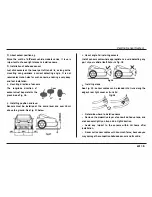
Remove the burrs from the hole edge with a round file
Insert the cables with sensors Into the holes made In bumper
•
Remarks
Use drill bit in appropriate diameter, sensors may not perform
perfectly In holes made by drl II bits In too small or large diameter
•
Sensors can be re-painted to match the colour of your vehicle,
but the painting layer must be symmetrical and below O.lmm
thick.
,. P-ering Up
=
Power connection of reverse aid system
The system gets power from the reverse I lght
of
vehicle. Refer to
Fig. 34 below.
(+)
(GND}
+12VDC
ROY9189
U�t
=
Power connection of parking aid system
•
Power connection of rear ECU
The rear ECU gets power from the reverse light of vehicle,
as shown in Fig. 34.
•
Power connection of front ECU
Parking Sensor System
Front ECU has
2
power cables, one is connected to ACC for power,
the other Is connected to the brake Ilg ht cable for the signal that
activates the system. See Fig. 35.
Fig.35
for
Front
=
How to use the cable clip
With the enclosed quick-on cable clips, system's power cable can
be
connected easily and perfectly with those of ACC, reverse or
brake lights.
Press the metal part tightly until you are sure that cables are well
connected. See Flg.36.
P<lw&rCablaot
IIJ20


